
fod optical detector fill light module

An optical detector and supplementary light technology, which is applied in the direction of optical device exploration, etc., can solve the problems of short service life, excessive infrared brightness, infrared camera cannot self-check supplementary light, etc., to achieve fault self-check and low power consumption Effect

Active Publication Date: 2021-08-31
成都航天凯特机电科技有限公司
View PDF6 Cites 0 Cited by
  • Summary
  • Abstract
  • Description
  • Claims
  • Application Information

AI Technical Summary

Problems solved by technology

[0011] Purpose of the present invention: Aiming at the defects in the prior art, the present invention provides a FOD optical detector supplementary light module to solve the problem that the prior art FOD optical detector adopts an infrared camera and cannot self-check the supplementary light fault, and the infrared brightness is too high. Strong image overexposure, severe heat generation and short service life

Method used


Image

  • fod optical detector fill light module
  • fod optical detector fill light module
  • fod optical detector fill light module

Examples


Embodiment 1

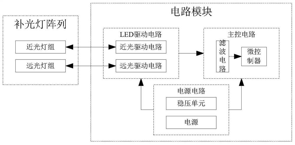
[0035] The supplementary light module of the FOD optical detector includes a supplementary light array, and a circuit module connected with the supplementary light array; the supplementary light array includes a low beam group and a high beam group, and the circuit module includes a power supply circuit, a main A control circuit and an LED drive circuit, the power supply circuit, the main control circuit and the LED drive circuit are electrically connected to each other, and the low beam group and the high beam group are both electrically connected to the LED drive circuit;

[0036] The power supply circuit is used to supply power to the main control circuit, the LED drive circuit, the low beam lamp group and the high beam lamp group;

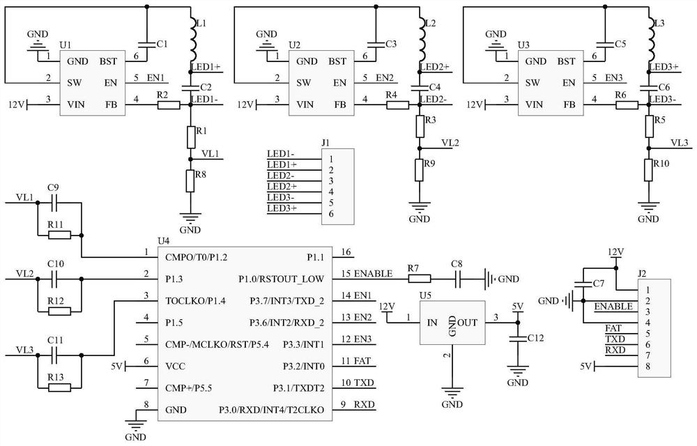
[0037] The LED drive circuit is used to obtain the voltage signals of the low beam light group and the high beam light group;

[0038] The main control circuit is used for receiving the voltage signal sent by the LED driving circuit and perform...

Embodiment 2

[0053] On the basis of the above-mentioned embodiments, in order to further and better implement the present invention, the following configuration is adopted in particular, the low-beam lamp group and the high-beam lamp group are both provided with cooling holes.

[0054] The FOD optical detector supplementary light module of the present invention has the following advantages through the setting of heat dissipation holes: 1. Increase the contact area between the low beam group and the high beam group and the air; 2. Increase air convection; 3. Increase heat dissipation efficiency ; 4. Reduce the weight of the fill light.


PUM


Abstract

The invention discloses a FOD optical detector supplementary light module and relates to the technical field of FOD optical detectors. Including a supplementary light array, and a circuit module connected to the supplementary light array; the supplementary light array includes a low beam group and a high beam group, and the circuit module includes a power supply circuit, a main control circuit and an LED drive circuit. The power supply circuit is used to supply power to the main control circuit, LED drive circuit, low beam lamp group and high beam lamp group; the LED drive circuit is used to obtain the voltage signal of the low beam lamp group and the high beam lamp group; the main control The circuit is used to receive the voltage signal sent by the LED drive circuit and perform diagnosis. The present invention uses the LED driving circuit of the circuit module to sample fault problems such as short circuit of the supplementary light, open circuit of the supplementary light, overcurrent of the supplementary light, etc., and diagnoses through a microcontroller to realize fault self-checking.

Description

technical field [0001] The invention relates to the technical field of FOD optical detectors, in particular to a supplementary light module for FOD optical detectors. Background technique [0002] FOD (Foreign Object Debris) is a foreign object that may damage aircraft and equipment on the ground of the airport runway activity area, or threaten the safety of airport staff and passengers, that is, certain foreign substances and debris that may damage aircraft or object. [0003] FOD optical detectors are generally used in hybrid detection equipment. Hybrid detection equipment includes radar detection equipment and optical detection equipment. There are two working modes: [0004] 1. Use radar detection equipment to scan and find FOD and measure its location by transmitting and receiving radio signals, and then feed back the location information to the photoelectric detection equipment. The photoelectric detection equipment uses photoelectric sensors to identify FOD, and fina...

Claims


Application Information

Patent Timeline
Patent Type & Authority Patents(China)
IPC IPC(8): G01V8/10
CPCG01V8/10
Inventor 杜德建蒋礼平陈鹏
Owner 成都航天凯特机电科技有限公司
Learn More