A regional energy station co-built with a substation

A technology of energy stations and substations, applied in the field of energy stations, can solve the problems of energy stations occupying a large space, poor switching stability, and affecting the use effect, so as to meet the energy supply requirements and improve the stability of power consumption

Active Publication Date: 2021-07-02
JIANGSU QUYU ENERGY CO LTD
View PDF6 Cites 0 Cited by
  • Summary
  • Abstract
  • Description
  • Claims
  • Application Information

AI Technical Summary

Problems solved by technology

[0004] 1. The energy supply system depends on a variety of energy sources. Except for electric energy, these energy sources are relatively restricted by regional conditions, resulting in many restrictions on the establishment of energy stations. This not only makes the construction cost of energy stations very high, but also limits the energy station. Promote application
[0005] 2. Since the energy station requires a large footprint, the construction cost is high
[0006] 3. Due to the dependence on a variety of energy sources, especially the pressure on the use of electric energy, and the poor switching stability between various energy supply modes, it affects the use effect

Method used


Image

  • A regional energy station co-built with a substation
  • A regional energy station co-built with a substation
  • A regional energy station co-built with a substation

Examples


Embodiment 1

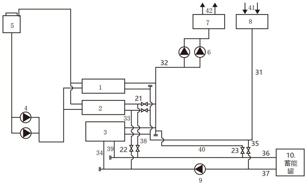
[0039] The present invention provides a regional energy station jointly built with a substation, which adopts the joint construction method of the energy station and the substation, such as Figure 11As shown, the substation is set on the ground, one side of the substation is the main transformer room, and the other side is a three-story construction design, in which each floor is reasonably arranged with a 10kV switch room (including grounding transformers, small resistance complete sets of devices and high-voltage cable shafts) , 10kV reactor room, 110kV GIS room, capacitor room, fire control room, secondary equipment room, battery room, office room and toilet, etc. Among them, the necessary space is designated as the power distribution room of the energy station, office room, etc.

[0040] Under the substation, the basement level and the second basement level are respectively set up. The basement level includes a cable interlayer, a fire protection water layer and a pump ro...

Embodiment 2

[0050] On the basis of the combined regional energy station in Embodiment 1, this embodiment puts the energy supply system in a separate cooling mode, and its operation mode is specifically:

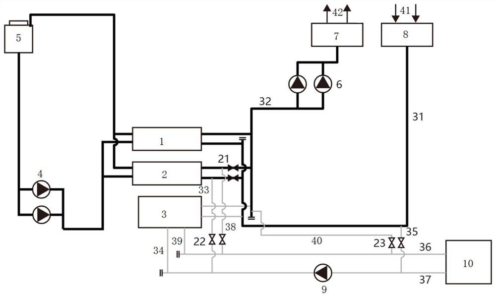
[0051] like figure 2 As shown, put the first centrifugal unit 1, the second centrifugal unit 2, the cooling pump 4, the cooling tower group 5, the cold-temperature pump 6, the water separator 7, and the water collector 8 into the running state, and put the electrode boiler 3, the energy storage pump 9 and the energy storage tank 10 are set to the non-operating state; then the first cold storage switching valve group 21 is opened, the second cold storage switching valve group 22 is closed, and the energy discharge switching valve group 23 is closed.

[0052] The trajectory of the individual refrigeration process of the energy supply system is as follows: figure 2 As shown by the bold line in , specifically:

[0053] The chilled water return water with high temperature at the user end ...

Embodiment 3

[0055] On the basis of the co-constructed regional energy station in Embodiment 1, this embodiment puts the energy supply system in a separate heating mode, and its operation mode is specifically:

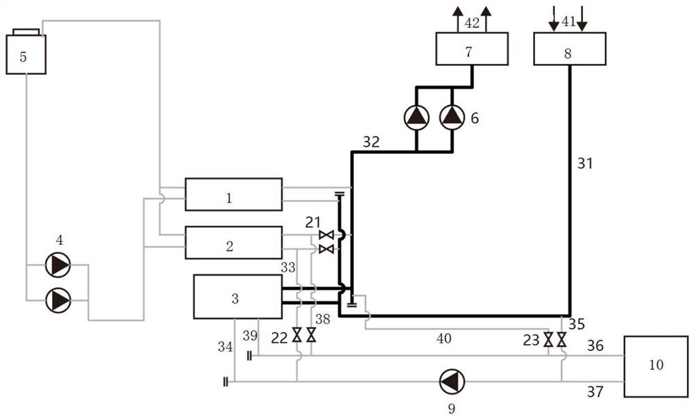
[0056] like image 3 As shown, the electrode boiler 3, the cold and warm pump 6, the water separator 7, and the water collector 8 are put into operation, and the first centrifugal unit 1, the second centrifugal unit 2, the cooling pump 4, the cooling tower group 5, and the energy storage pump 9 and the energy storage tank 10 are set to the non-operating state; the first cold storage switching valve group 21 is closed, the second cold storage switching valve group 22 is closed, and the energy discharge switching valve group 23 is closed.

[0057] The individual heating process trajectory of the energy supply system is as follows: image 3 As shown by the bold line in , specifically:

[0058] The hot water return water with a lower temperature at the user end passes through the ene...


PUM


Abstract

The invention discloses a regional energy station jointly built with a substation, including a substation and an energy station, the energy station includes an energy supply system and an energy station room for arranging the energy supply system, and the energy station room is set up in Under the ground of the substation, the energy supply system includes the first centrifugal unit, the second centrifugal unit, electrode boiler, energy storage tank, cooling tower group, cooling pump, cold temperature pump, energy storage pump, energy supply return water main pipe, energy supply water supply Main pipe, cold storage water supply branch pipe, cold storage return water branch pipe, heat storage water supply branch pipe, heat storage return water branch pipe, energy discharge water supply main pipe, energy discharge return water main pipe, energy storage and discharge water supply main pipe, and energy storage and discharge return water main pipe. Through the innovative design of the energy supply system, the invention enables the regional energy station to be co-constructed with the substation, and adopts the co-construction method, which saves land resources and improves system efficiency.

Description

technical field [0001] The invention relates to the field of energy stations, in particular to a regional energy station that can be jointly built with a substation. Background technique [0002] A substation refers to a place in the power system that transforms voltage and current, receives electric energy and distributes electric energy. Its location is determined according to a certain power supply radius principle, and the capacity is allocated according to the load demand of buildings in the supply area. Among them, the cooling power load Accounting for 25-60%, it is used to meet the needs of traditional decentralized and independent cooling and heating systems. [0003] The energy station is mainly to realize the energy supply for users in a certain surrounding area, and to provide unified cooling, heating and hot water supply to the buildings. The existing energy station adopts an intensive energy supply system, which is a decentralized, An independent cooling and he...

Claims


Application Information

Patent Timeline
Patent Type & Authority Patents(China)
IPC IPC(8): F24F5/00F24F11/84F24F11/89F24F13/30E04H5/02E04H5/04
CPCE04H5/02E04H5/04F24F5/0003F24F5/0017F24F13/30F24F11/84F24F11/89Y02E60/14
Inventor 蒋家祺薛中柱
Owner JIANGSU QUYU ENERGY CO LTD
Why Eureka
Try Eureka