Device and method for testing friction force of cylinder liner and piston assembly

A technology of piston assembly and testing device, applied in measuring devices, force/torque/work measuring instruments, instruments, etc., can solve problems such as lack of deviation between measured values ​​and actual values, and reduce the influence of tightening pressure on test results. Eliminate the interference of test results and the effect of accurate test results

Active Publication Date: 2017-06-13
DALIAN MARITIME UNIVERSITY +1
View PDF1 Cites 0 Cited by
  • Summary
  • Abstract
  • Description
  • Claims
  • Application Information

AI Technical Summary

Problems solved by technology

[0003] In the present invention, the air inlet and the air outlet are arranged on the piston, so that the high-pressure gas enters from the air inlet, exits from the air outlet, and finally acts on the back of the first air ring, the second air ring, and the contact surface of the cylinder liner. , to achieve radial loading on multiple piston rings to simulate the radial pressure on the piston rings in the ignition state; at the same time, only rely on the cylinder liner's own weight to seal the cylinder liner with the cylinder body, so that the cylinder liner is "floating" relative to the cylinder body " state, through the friction sensor fixed in the gap between the baffle plate and the cylinder block, the motor is used to drag the diesel engine backwards to measure the friction force between the cylinder liner and the piston assembly, so as to solve the problem of measuring the friction between the cylinder liner and the piston assembly by the backward dragging method During power consumption, due to the lack of radial loading pressure on the piston ring, there is a large deviation between the measured value and the actual value

Method used


Image

  • Device and method for testing friction force of cylinder liner and piston assembly
  • Device and method for testing friction force of cylinder liner and piston assembly
  • Device and method for testing friction force of cylinder liner and piston assembly

Examples


Embodiment 1

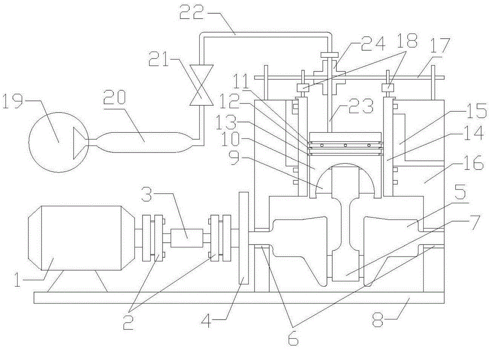
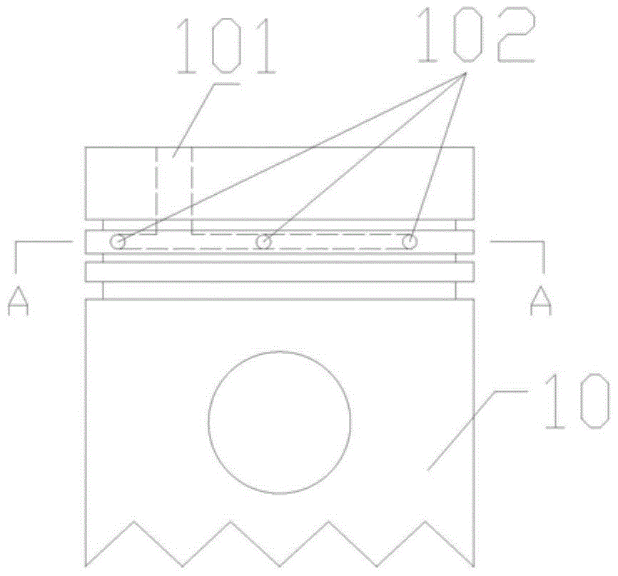
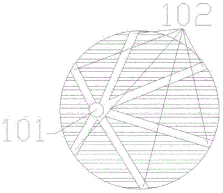
[0024] A test device for the friction force of a cylinder liner and a piston assembly, the device includes a motor 1, a coupling 2, a torque sensor 3, a flywheel disc 4, a crankshaft 5, a bearing 6, a connecting rod 7, a support platform 8, and a piston pin 9 , piston 10, air intake hole 101, air outlet hole 102, first air ring 11, second air ring 12, scraper ring 13, cylinder liner 14, heating / cooling chamber 15, cylinder block 16, baffle plate 17, Friction sensor 18, air compressor 19, high pressure cylinder 20, pressure reducing valve 21, high pressure hose 22, high pressure hard pipe 23, guide rail 24, described motor 1 and cylinder body 16 are fixed on the support platform 8, described The motor 1 is connected with the crankshaft 5 through the shaft coupling 2, the torque sensor 3, the flywheel disc 4, the crankshaft 5 is fixed on the cylinder block 16 through the bearing 6, one end of the connecting rod 7 is connected with the crankshaft 5, and the connecting rod The oth...

Embodiment 2

[0026] A method utilizing the device described in Embodiment 1 to test the frictional force of the cylinder liner and the piston assembly, said method comprising the steps of:

[0027] Open the heating / cooling chamber 15, and adjust the temperature of the inner wall of the cylinder liner 14 to 70°C;

[0028] ② Turn on the motor 1, the motor 1 drives the crankshaft 5 to rotate, and the crankshaft 5 drives the connecting rod 7 to convert the rotational motion into the reciprocating motion of the piston 10;

[0029] ③ Turn on the air compressor 19, adjust the air pressure to 10MPa, so that the high-pressure gas enters from the air inlet 101 and exits from the air outlet 102, and applies radial pressure to the first air ring 11 and the second air ring 12;

[0030] ④ The friction force between the first air ring 11, the second air ring 12, the piston 10 and the cylinder liner 14 is transmitted to the friction force sensor 18 through the cylinder liner 14 for measurement.


PUM


Abstract

The invention relates to a device and method for testing the friction force of a cylinder liner and a piston assembly, belonging to the technical field of friction and wear testing. The power unit of the device is connected to the piston through a piston pin, and the piston passes through a first The first air ring, the second air ring, and the oil scraper ring are sealed and connected with the cylinder liner. The cylinder liner is sealed and fixed in the cylinder body with a heating / cooling chamber, and the baffle is fixed on the cylinder body so that the gap between the baffle plate and the cylinder body A gap is formed between the friction sensor and the friction sensor is fixed in the gap between the baffle and the cylinder body. The air supply unit is connected to the air inlet hole of the piston. The piston is installed in the ring groove I of the first air ring and the second air ring. A number of air outlet holes are evenly distributed along the circumference of the piston at the position between the ring grooves II. The beneficial effect of the present invention is that the device adopts high-pressure gas to simulate gas pressure, and implements radial loading on multiple piston rings, eliminating the need for mechanical radial loading. The constraint on the rotation of the piston ring in the circumferential direction is closer to the motion state of the piston ring in the ignition state.

Description

technical field [0001] The invention relates to a device and a method for testing the friction force of a cylinder liner and a piston assembly, belonging to the technical field of friction and wear testing. Background technique [0002] At present, the research on the friction power consumption of the cylinder liner and piston assembly generally adopts the backward drag method, and this method is tested in the non-ignition state. Due to the lack of radial loading pressure on the piston ring, the measured friction power consumption is different from that under the actual working state. The difference is large. The patent "A Cylinder Liner Piston Ring Parts Friction and Wear Test Equipment" (Patent No.: ZL 200520146126.6) for radial loading of piston rings adopts disc springs to mechanically load piston rings radially, which can simulate the ignition of piston rings. However, the mechanical radial loading method limits the movement of the piston ring in the circumferential di...

Claims


Application Information

Patent Timeline
Patent Type & Authority Patents(China)
IPC IPC(8): G01L5/00
Inventor 徐久军单英春袁晓帅韩晓光沈岩刘德良郝勇刚朱峰金梅张凯陈泽忠
Owner DALIAN MARITIME UNIVERSITY
Why Eureka
Try Eureka