Power station boiler flame center position monitoring method

A flame center, power station boiler technology, applied in the combustion method, the safety device of the combustion chamber, the combustion chamber, etc., can solve the problems affecting the economy and safety of the boiler, the inability to know the combustion condition of the furnace, and the unfavorable combustion adjustment, etc. Optimize boiler combustion economy, avoid furnace combustion deterioration, and avoid unreasonable combustion effects

Active Publication Date: 2020-11-17
CHINA DATANG CORP SCI & TECH RES INST CO LTD EAST CHINA BRANCH +1
View PDF7 Cites 0 Cited by
  • Summary
  • Abstract
  • Description
  • Claims
  • Application Information

AI Technical Summary

Problems solved by technology

[0003] The current power plant boiler is running without a measuring device for the center of the furnace flame, so it is impossible to know the actual combustion status in the furnace. The relative temperature of the flame center can only be judged indirectly by the temperature of the water-cooled wall temperature, the metal wall temperature of the heating surface at the tail, and the temperature of the reheated steam. The position is not intuitive, but the change of wall temperature and steam temperature seriously lags behind the change of flame (flue gas) temperature, which is not conducive to combustion adjustment and affects boiler economy and safety. In the prior art, such as the application number CN201710151752.1 The Chinese invention patent discloses a method for monitoring the center position of the boiler furnace flame, which establishes a prediction model for the heat load of the furnace and the center position of the furnace flame, and establishes the relationship between the heat load of the furnace and the temperature of the water-cooled wall according to the heat transfer characteristics in the furnace As well as the corresponding relationship between the furnace heat load distribution and the water-cooled wall temperature distribution, the essence is to use the wall temperature of the furnace water-cooled wall to predict the position of the flame center
On the one hand, a place with high wall temperature does not necessarily mean high heat load and high flue gas temperature; on the other hand, the response of wall temperature lags behind the change of flue temperature (flame temperature) seriously, and the regulation is poor

Method used


Image

  • Power station boiler flame center position monitoring method
  • Power station boiler flame center position monitoring method

Examples


Embodiment Construction

[0033] In order to make the purpose, technical solutions and advantages of the embodiments of the present invention clearer, the technical solutions in the embodiments of the present invention will be clearly and completely described below in conjunction with the embodiments of the present invention. Obviously, the described embodiments are part of the present invention Examples, not all examples. Based on the embodiments of the present invention, all other embodiments obtained by persons of ordinary skill in the art without creative efforts fall within the protection scope of the present invention.

[0034] A method for monitoring the flame center position of a utility boiler, comprising the following steps:

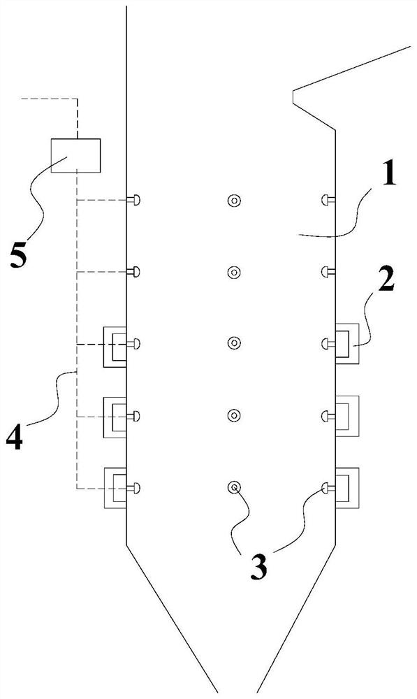
[0035] s1. Arrangement of temperature measuring components 3:

[0036] like figure 1 As shown, there are n layers of burners 2 arranged at equal intervals in the boiler furnace 1, and the number of burner 2 layers is set according to the actual situation of the boiler...


PUM


Abstract

The invention relates to the field of power station boiler monitoring, in particular to a power station boiler flame center position monitoring method. The method includes the steps that arranging temperature measuring elements, calculating the average temperature of each layer of the temperature measuring elements, calculating the difference between the temperature of the temperature measuring elements and the average temperature, calculating the average value of the average temperature of three adjacent layers of the temperature measuring elements, taking a group with the highest average temperature of the three adjacent layers of the temperature measuring elements, and the position of the layer of the temperature measuring elements with the highest average temperature in the group is the boiler flame center position. The power station boiler flame center position monitoring method has the advantages that by measuring the flame temperature of a boiler hearth combustor area and then calculating the flame center position according to the detected temperature, boiler flame center position monitoring is accurate, which can not only guide the air distribution and operation of a combustor, but also avoid unreasonable combustion. The combustion economy of a boiler is optimized, and the reheating steam temperature can be adjusted by changing the flame center position.

Description

technical field [0001] The invention relates to the field of power plant boiler monitoring, in particular to a method for monitoring the central position of a power plant boiler flame. Background technique [0002] Boilers are the main production equipment of thermal power generation enterprises. The economy and stability of boiler operation are related to the competitiveness and safety of power generation enterprises. How to improve the efficiency of thermal power generation units and reduce energy consumption has become an urgent task for the technical transformation of thermal power plants. The boiler system is a complex control system, in which the combustion system is a multi-input, multi-output, strong coupling, multi-interference, large lag and difficult to establish an accurate mathematical model of the control object, but also the key to the safe and economical operation of thermal power generation equipment factor. Therefore, determining the position of the flame...

Claims


Application Information

Patent Timeline
IPC IPC(8): F23M11/04
CPCF23M11/045
Inventor 韩磊邓中乙马启磊潘存华李冬方军庭彭志福
Owner CHINA DATANG CORP SCI & TECH RES INST CO LTD EAST CHINA BRANCH
Why Eureka
Try Eureka