A constant speed hydraulic drive device

A driving device and constant speed technology, applied in the direction of fluid pressure actuating devices, mechanical equipment, etc., can solve the problems of inconvenient oil change, incomplete cleaning, pipeline blockage, etc., to avoid the decline of new oil quality and facilitate disassembly The effect of operation, convenient installation and positioning

Active Publication Date: 2022-05-03
安徽肥地肥业有限责任公司
View PDF18 Cites 0 Cited by
  • Summary
  • Abstract
  • Description
  • Claims
  • Application Information

AI Technical Summary

Problems solved by technology

[0005] The purpose of the present invention is to provide a constant-speed hydraulic drive device to solve the inconvenient work of disassembling the pipeline proposed by the above-mentioned background technology, which is not conducive to the subsequent cleaning of the pipeline, resulting in the pipeline being prone to blockage after long-term use At the same time, it is not conducive to the installation and fixing of pipes of various calibers, which reduces the applicability of the overall device, and is inconvenient to disassemble and replace the fuel tank, so that the cleaning of the old oil in the fuel tank is not complete enough, resulting in oil change The work is not convenient enough, which affects the operation efficiency of the follow-up overall device

Method used


Image

  • A constant speed hydraulic drive device
  • A constant speed hydraulic drive device
  • A constant speed hydraulic drive device

Examples


Embodiment Construction

[0028] The technical solutions of the present invention will be clearly and completely described below in conjunction with the embodiments. Apparently, the described embodiments are only some of the embodiments of the present invention, not all of them. Based on the embodiments of the present invention, all other embodiments obtained by persons of ordinary skill in the art without creative efforts fall within the protection scope of the present invention.

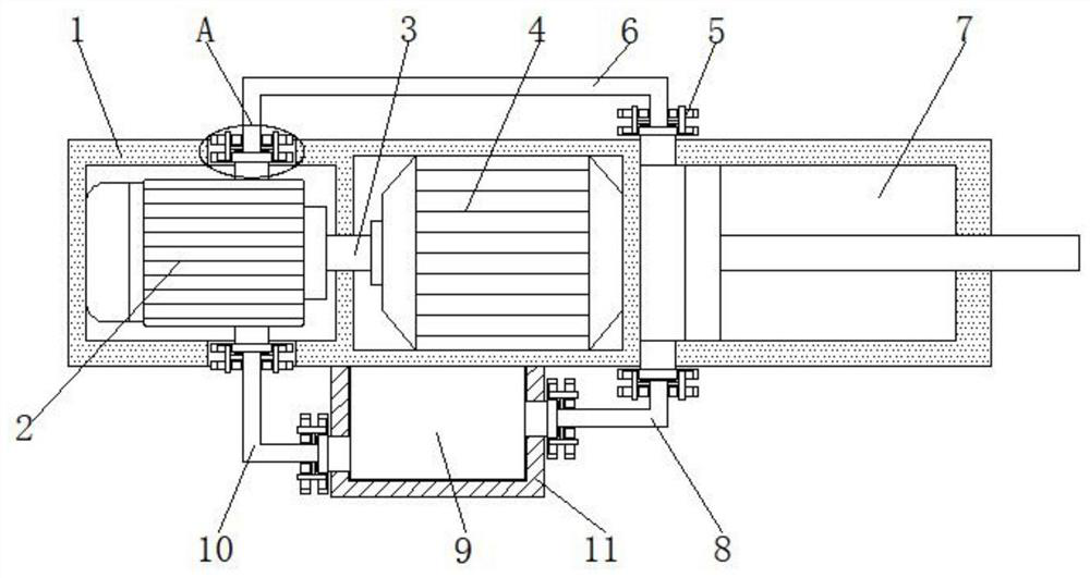
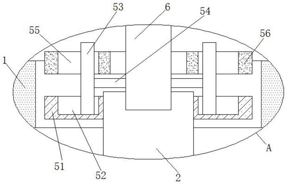
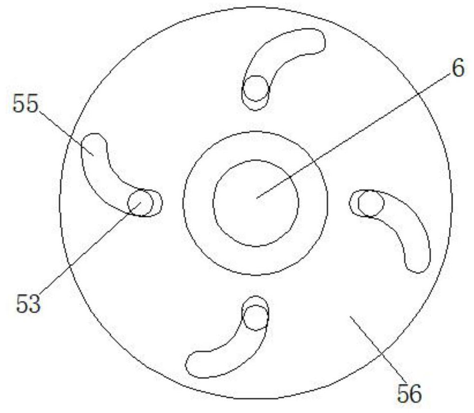
[0029] see Figure 1-8 As shown, a constant-speed hydraulic drive device includes a drive device main body 1, a constant-speed hydraulic pump 2, a drive shaft 3, a motor 4 and a hydraulic chamber 7, and a constant-speed hydraulic pump 2 and a motor 4 are respectively arranged inside the drive device main body 1. , the constant speed hydraulic pump 2 is rotationally connected with the drive shaft 3, the drive shaft 3 is fixedly connected with the motor 4, the outlet of the constant speed hydraulic pump 2 is connected with th...


PUM


Abstract

The invention discloses a constant-speed hydraulic driving device, which comprises a main body of the driving device, a constant-speed hydraulic pump, a drive shaft, a motor and a hydraulic cavity. The main body of the driving device is respectively provided with a constant-speed hydraulic pump and a motor. It is rotatably connected with the driving shaft, and the driving shaft is fixedly connected with the motor. The outlet of the constant-speed hydraulic pump is connected to the first pipeline through the connecting device. The first pipeline is connected to the inlet of the hydraulic chamber through the connecting device. The hydraulic chamber is opened in the main body of the driving device. Inside, the outlet of the hydraulic chamber is interconnected with the second conduit via a connecting device. In the constant-speed hydraulic drive device, the water pipes are connected to the inlets and outlets through the connecting device. The connecting device includes a fixed block. The staff can place the shifting block above the fixed block to make the limit groove opened in the shifting block Engaged with the connecting rod, and then by rotating the shift block, the shift block drives the limit groove to rotate, and the limit groove squeezes the connecting rod when rotating.

Description

technical field [0001] The invention belongs to the field of constant-speed hydraulic drive, and in particular relates to a constant-speed hydraulic drive device. Background technique [0002] The constant-speed hydraulic drive device mainly uses liquid as the working medium, converts the mechanical energy of the prime mover into hydraulic pressure energy through the hydraulic pump, and then converts the pressure energy of the liquid into mechanical energy through the pipeline with the help of the actuator, thereby realizing linear or rotary motion , but the following problems generally exist when the existing constant speed hydraulic drive device is in use; [0003] 1. It is inconvenient to disassemble the pipeline, which is not conducive to the subsequent cleaning of the pipeline, resulting in the phenomenon that the pipeline is prone to blockage after long-term use. At the same time, it is not conducive to the installation and fixing of pipelines with various calibers, wh...

Claims


Application Information

Patent Timeline
Patent Type & Authority Patents(China)
IPC IPC(8): F15B15/02
CPCF15B15/02F15B2215/30
Inventor 张荣号张维秀侯强张梅侯祥辉程琛
Owner 安徽肥地肥业有限责任公司
Why Eureka
Try Eureka