an electric shaver

An electric shaver, active technology, applied in metal processing, etc., can solve problems such as increased load, leakage of sealing ring, increased noise, etc.

Active Publication Date: 2022-08-05
HUANXING TECH HANGZHOU CO LTD
View PDF8 Cites 0 Cited by
  • Summary
  • Abstract
  • Description
  • Claims
  • Application Information

AI Technical Summary

Problems solved by technology

The disadvantages of this method are obvious: increased noise, increased load, and the seal ring is required to seal the pivot shaft. Long-term use will cause leakage of the seal ring after aging and wear.
[0003] There is also an electric shaver, such as the structure disclosed in reference document 1 (201820512427.3), which adopts a magnetic attraction method to connect the hand-held part and the cutter head part, such as figure 1 As shown, it includes the motor 10 located on the central axis, and the upper magnet 30 located on the upper part, and the lower magnet 20 located on the lower part. Through this magnetic attraction method, the hand-held part and the cutter head part are connected to solve the problem of aging and wear of the sealing ring. Leakage occurs; but this assembly method also brings new problems, because the upper magnet and the lower magnet are arranged on the central axis of the electric shaver, and the motor needs to function as the lower magnet, that is, the output shaft of the motor is directly connected to the lower magnet. Magnet connection, that is, it must be ensured that the motor is also set on the central axis of the electric shaver

Method used


Image

  • an electric shaver
  • an electric shaver
  • an electric shaver

Examples


Embodiment 1

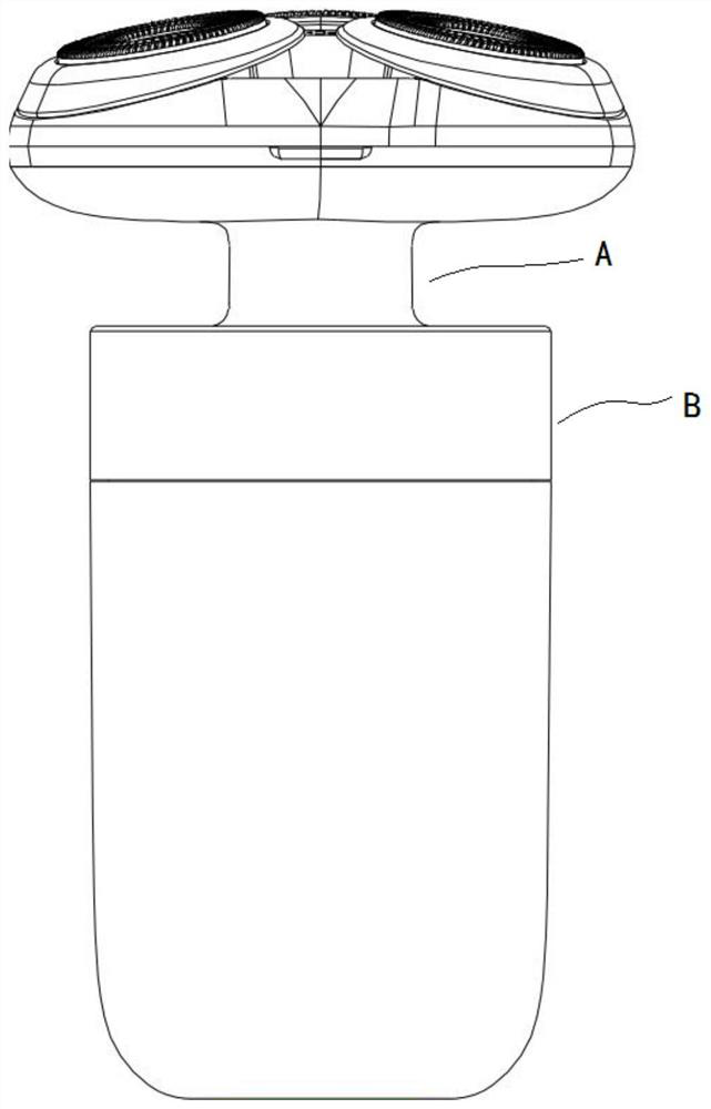
[0044] refer to Figure 2-Figure 4 As shown, an electric shaver includes a main body assembly and a head cover assembly, the head cover assembly is provided on the main body assembly, and the main body assembly includes a lower casing B and a drive provided in the lower casing B The head cover assembly includes a moving knife unit and an upper casing A for supporting the moving knife unit, the lower casing is embedded with an active magnetic assembly, and the upper casing is embedded with a driven magnetic assembly. When the knife is stationary and placed vertically, the magnetism corresponding to the longitudinal direction of the active magnetic component and the driven magnetic component is in a state of opposites attracting each other. Drive rotation under the action of the component and the driven magnetic component; the central axes of the active magnetic component and the driven magnetic component coincide with the central axis of the electric shaver, and the central axi...

Embodiment 2

[0053] As Example 1, the assembly of the eccentric motor and the gear assembly is given to realize the way of magnetic attraction.

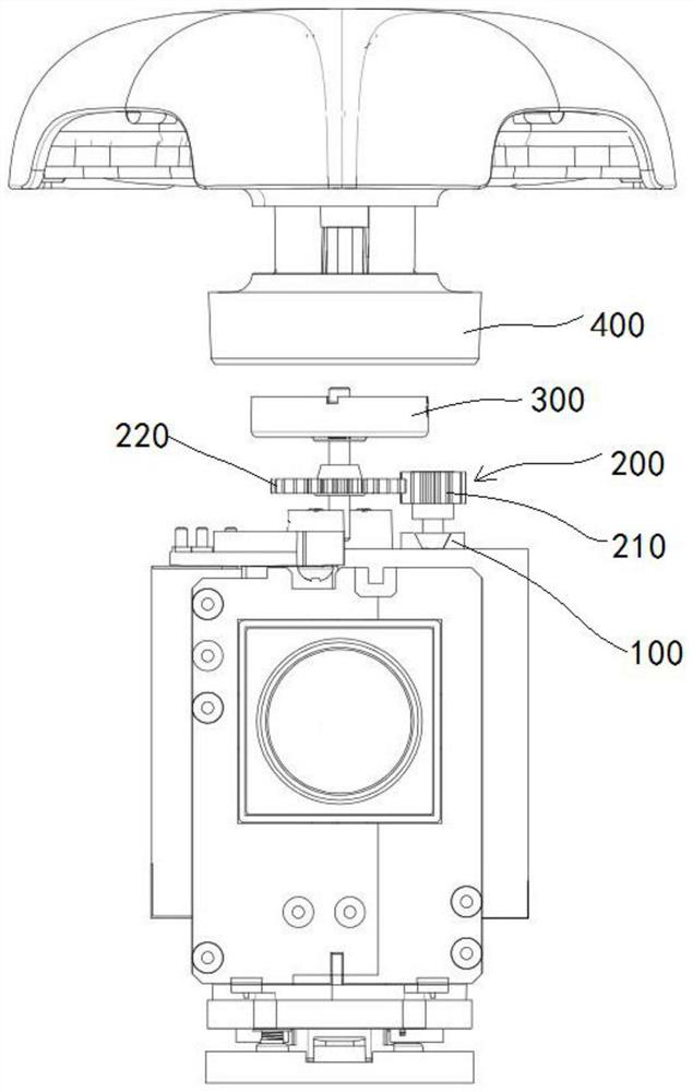
[0054] refer to Figure 5 As shown, the electric shaver includes a motor bracket 500, the motor 100 is fixed on the lower housing B through the motor bracket 500, the motor bracket 500 covers the upper end of the motor, and the drive shaft 110 of the motor 100 penetrates through The motor bracket 500 is then connected to the gear assembly 200 .

[0055] Since the motor will vibrate to a certain extent during the rotation process, in order to reduce the vibration, a fixed motor bracket is used, and the motor bracket only fixes the upper end of the motor. Since the output force of the drive shaft is output from the drive shaft, the upper end of the motor is firmly A firm fixation achieves the desired effect of maximizing the technical effect of reducing vibration with very little material.

[0056] Further, the active magnetic assembly adopts the...

Embodiment 3

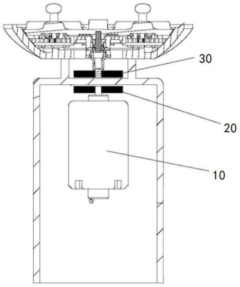
[0066] refer to Figure 7 As shown, in this solution, the auxiliary magnetic attraction component includes a lower auxiliary magnet 310 and an upper auxiliary magnet 410, and the magnetism corresponding to the longitudinal direction of the lower auxiliary magnet and the upper auxiliary magnet is in a state of opposites attracting each other.

[0067] Compared with the active magnet and the driven magnet, the auxiliary magnetic assembly can rotate and rotate, and it is in a static state, that is, the corresponding lower auxiliary magnet and upper auxiliary magnet are firmly fixed in the installation position, and the auxiliary magnetic assembly only serves as a pure suction. The combined function is used to connect the lower casing with the upper casing, regardless of the changes of other components inside the upper casing and the lower casing, the function is focused.

[0068]The active magnet and the driven magnet of Example 1-Example 3 are identified as the main magnetic att...


PUM


Abstract

The present invention provides an electric shaver, including a main body assembly and a head cover assembly, the main body assembly includes a lower casing and a drive unit disposed in the lower casing, the head cover assembly includes a moving knife unit and a user In the upper casing supporting the moving knife unit, the lower casing is embedded with an active magnetic component, and the upper casing is embedded with a driven magnetic component. When the electric shaver is stationary and placed vertically, the active magnetic The magnetism corresponding to the longitudinal direction of the component and the driven magnetic component is in a state of attraction of opposites, the driving unit includes a motor, and the moving knife unit is driven to rotate under the action of the motor, the active magnetic component and the driven magnetic component; the The central axes of the active magnetic assembly and the driven magnetic assembly coincide with the central axis of the electric shaver, and the central axis of the motor is deviated from the central axis of the electric shaver by 4-8 mm. Wherein the motor is deviated from the central axis of the electric shaver, and the vibration generated by the rotation of the motor has the least influence on the magnet itself.

Description

technical field [0001] The invention relates to the field of household appliances, in particular to an electric shaver. Background technique [0002] An existing electric shaver includes a hand-held part and a cutter head part, wherein the transmission of the hand-held part and the cutter head part is transmitted by a pivot shaft extending from the hand-held part through the coupling shaft of the cutter head part to transmit torque. The disadvantages of this method are obvious: it increases the noise, increases the load, and requires a sealing ring to seal the pivot. Long-term use will cause the sealing ring to age and wear out, resulting in leakage. [0003] There is also an existing electric shaver, such as the structure disclosed in the reference document 1 (201820512427.3), which adopts a magnetic suction method to connect the hand-held part and the cutter head part, such as figure 1 As shown, it includes a motor 10 located on the central axis, an upper magnet 30 locate...

Claims


Application Information

Patent Timeline
Patent Type & Authority Patents(China)
IPC IPC(8): B26B19/38B26B19/14B26B19/28
CPCB26B19/3806B26B19/14B26B19/28
Inventor 祝永锋叶志文肖林
Owner HUANXING TECH HANGZHOU CO LTD
Why Eureka
Try Eureka