
Configurable luminaires and components

An illuminator, adjustable technology, applied in the field of optics, which can solve problems such as low optical efficiency

Pending Publication Date: 2020-11-13
闪耀光电公司
View PDF24 Cites 0 Cited by
  • Summary
  • Abstract
  • Description
  • Claims
  • Application Information

AI Technical Summary

Problems solved by technology

US Patent 2,753,487 to Bone teaches the use of angled apertures on light sources that only allow light from a small area to reach the optics, effectively creating an angled point source of light but providing very low optical efficiency

Method used


Image

  • Configurable luminaires and components
  • Configurable luminaires and components
  • Configurable luminaires and components

Examples


Embodiment Construction

[0076] Part 1: Light Mix Pass

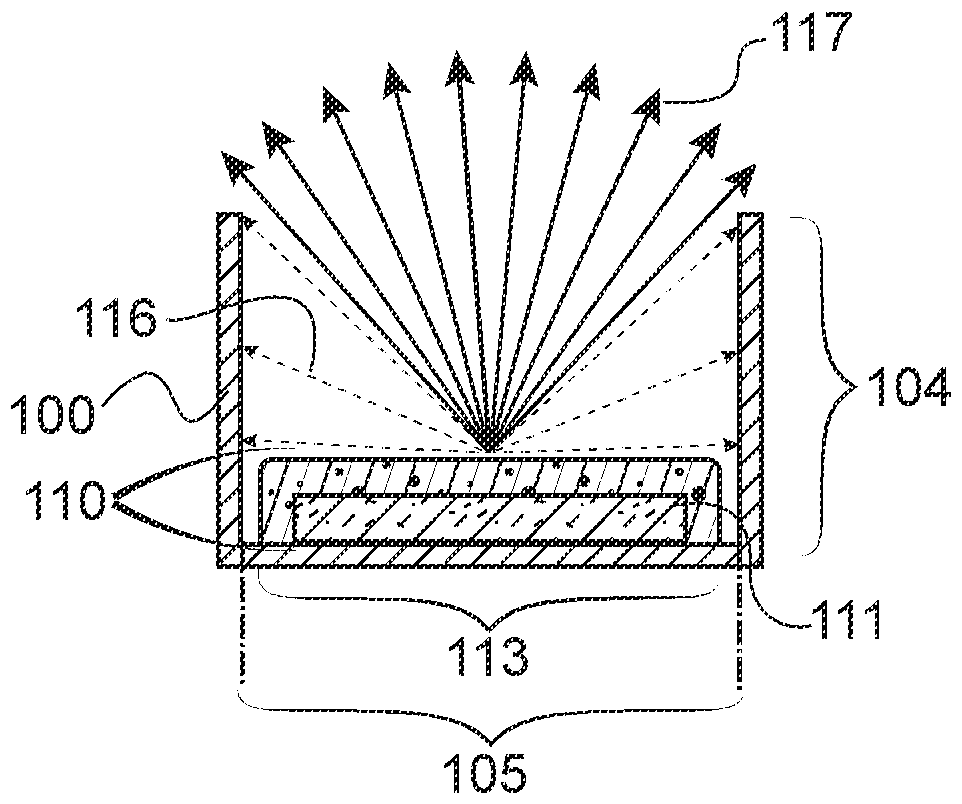
[0077] figure 2 A preferred embodiment is shown in which mixing channel 100 and light emitter 110 are paired together. The mixing channel 100 has at least two openings. The input opening 101 is placed around all or nearly all of the perimeter of the light emitter such that all or most of the light emitted by the light emitter 110 enters the mixing channel 100 . The light emitter 110 can be a single LED (phosphor-converted or non-phosphor-converted), an array of LEDs (phosphor-converted or non-phosphor-converted), an array of LEDs covered with a common phosphor-converted layer, or other source of light emission. exist figure 1 , figure 2 , Figure 3, Figure 7 and Figure 8, a single phosphor-converted LED is shown. The output opening 102 allows light to exit the mixing channel 100 . The mixing channel 100 has a reflective inner surface 103 and a shape designed to provide sufficient light mixing such that light exiting the output opening...


PUM


Abstract

A steerable illumination fixture includes an emitting source and a refractive optical system that steers an emitted beam by relative translation of the emitting source against the optical system. Thelight emitting source may be placed along an optical axis of one or more lenses to produce an output beam along that axis, or translated in-plane (orthogonal to the optical axis) relative to the lenses to produce a steered beam. The optical system may include refractive lenses and in some embodiments mixing channels and / or one or more baffles with apertures. The design is typically optimized to produce a round, uniform beam that retains approximately the same power level and beam width as it is steered. It is beneficial, but not required, that a second lens have a diameter equal to or larger than a first lens. The lenses may be configured so that the effective focal plane of the two lenses together is located approximately at the plane of the light emitting source.

Description

[0001] Cross References to Related Applications [0002] This patent application claims priority to the following U.S. Provisional Patent Applications, each of which is incorporated herein by reference in its entirety: Serial No. 62 / 590,649 filed November 27, 2017 by Andrew Kim et al; Serial No. 62 / 590,650 filed November 27, 2017 by Andrew Kim et al.; and Serial No. 62 / 653,754 filed April 6, 2018 by John Lloyd. technical field [0003] This patent application relates to optics, and more particularly to optical systems for controlling beam characteristics in illumination. Background technique [0004] 1. LED light source uniformity and angular distribution [0005] Light-emitting diodes (LEDs) are widely used in lighting systems as energy-saving, long-life light sources. figure 1 A typical phosphor converted LED 109 design is shown. It consists of an LED chip 111 and a phosphor coating 112 . The phosphor coating 112 down converts some of the short wavelength light emitt...

Claims


Application Information

Patent Timeline
IPC IPC(8): F21V7/00F21V7/04F21V14/00F21V14/04
CPCF21V5/007F21V5/008F21V7/043F21V14/02F21V14/06F21V17/105F21Y2105/10F21K9/62F21Y2115/10F21S41/30F21S41/141F21S41/20F21V13/04
Inventor C·格拉登A·金P·科佐多伊J·罗伊德
Owner 闪耀光电公司
Learn More