
Permanent magnet brushless direct current motor

A permanent magnet brushless DC and permanent magnet technology, which is applied in the direction of electrical components, electromechanical devices, electric components, etc., can solve problems that affect the service life of brushless DC motors, difficult motor maintenance and replacement, etc., so as to facilitate quick disassembly and maintenance operations, Improved cushioning and shock absorption effect, high impact absorption effect

Inactive Publication Date: 2020-11-13
姚宇翔
View PDF0 Cites 0 Cited by
  • Summary
  • Abstract
  • Description
  • Claims
  • Application Information

AI Technical Summary

Problems solved by technology

[0003] However, the biggest disadvantage of the existing permanent magnet brushless DC motor is that it is difficult to use in an environment with corrosiveness and high vibration frequency. When the motor needs to be repaired, because the motor has been used for a long time and rusted and bonded to the connected parts, it is difficult to quickly repair and replace the motor. At the same time, the service life of the brushless DC motor is easily affected due to the high vibration frequency.

Method used


Image

  • Permanent magnet brushless direct current motor
  • Permanent magnet brushless direct current motor
  • Permanent magnet brushless direct current motor

Examples


Embodiment approach

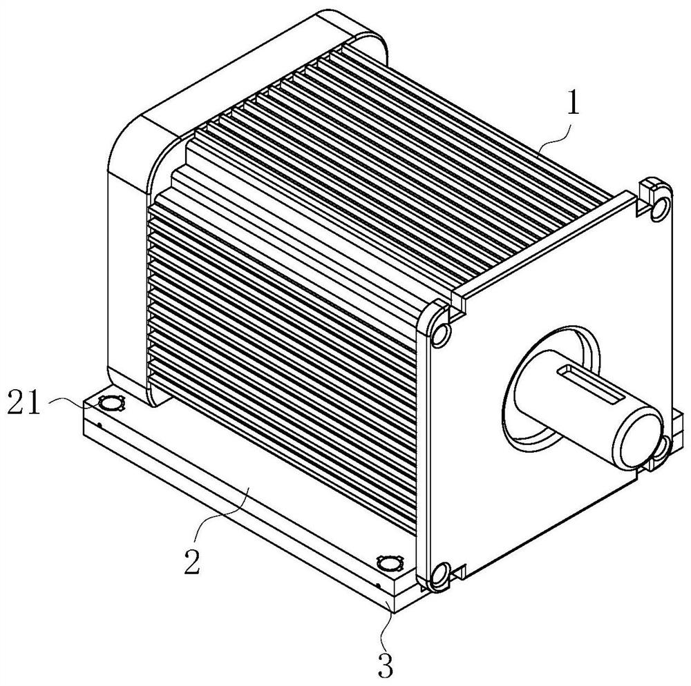
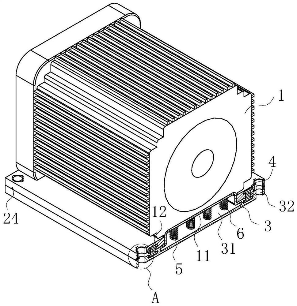
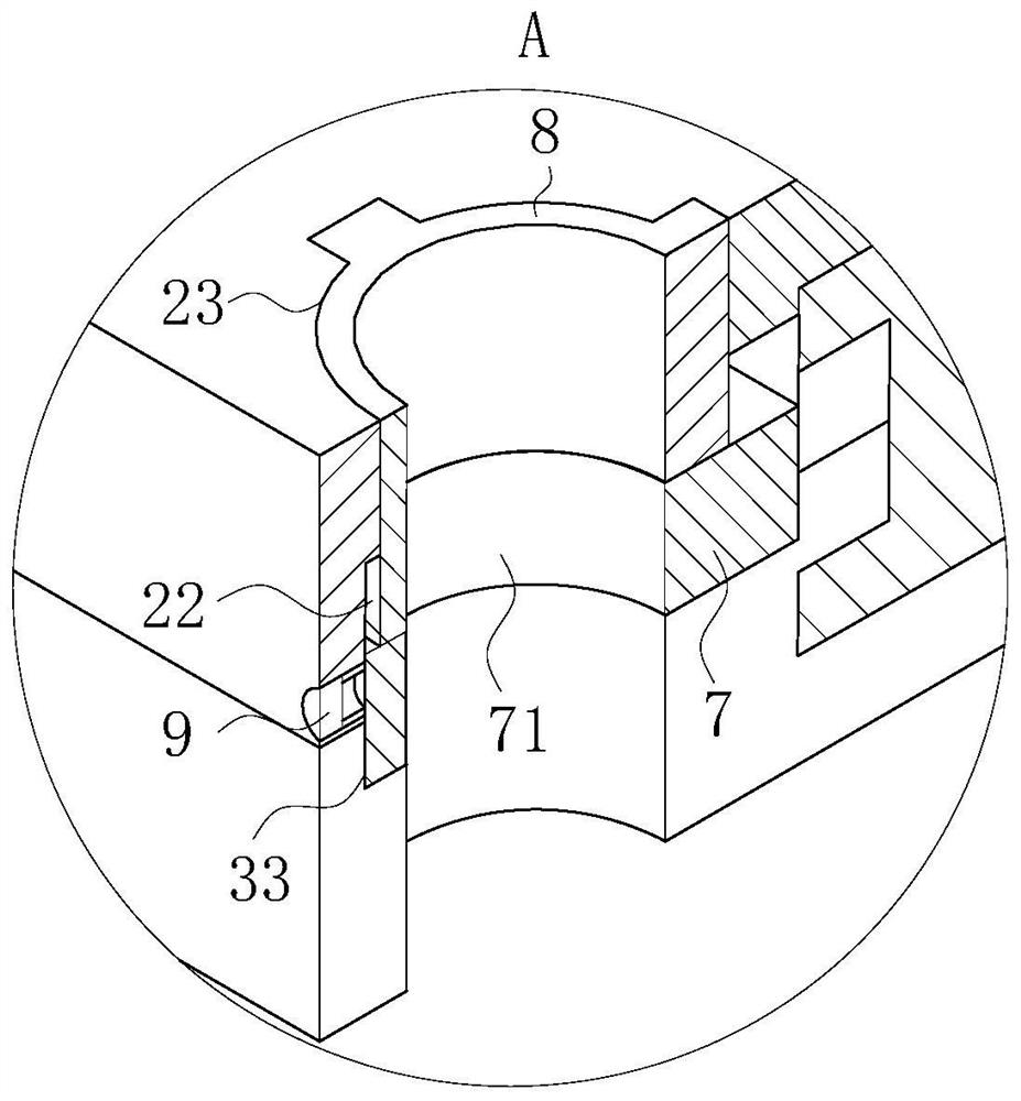
[0024] As an embodiment of the present invention, the lower end surface of the mounting plate 2 is provided with a plurality of limiting cavities 22, and the limiting blocks 7 are slidingly arranged in the plurality of limiting cavities 22; the plurality of limiting cavities 22 The depth is greater than the thickness of the limit block 7; the upper end surface of the limit block 7 is connected to the limit cavity 22 through the limit spring; the upper end surface of the two side walls of the fixed base 3 is provided with a plurality of insertion cavities 33, And a plurality of insertion cavities 33 are respectively aligned with a plurality of limiting cavities 22; a plurality of said insertion cavities 33 are slidably inserted into the limiting block 7, and the thickness of the limiting block 7 is greater than the depth of the insertion cavity 33; when working, when When the machine housing 1 is slidably installed on the upper end surface of the fixed base 3, it is necessary to...


PUM


Abstract

The invention belongs to the technical field of motors, and particularly relates to a permanent magnet brushless direct current motor. The permanent magnet brushless direct current motor comprises a motor shell, wherein a rotor assembly is arranged in the motor shell and arranged outside a rotating shaft in a sleeving mode to drive the rotating shaft to rotate around the axis of the rotating shaft; a sliding groove cavity is formed in the lower end face of the motor shell, and mounting plates are arranged on the two sides of the sliding cavity; a T-shaped sliding groove is formed in the bottomend face of the mounting plate, and a plurality of connecting holes are formed in the mounting plate; a fixed base is slidably inserted into the sliding cavity, and the upper end faces of the two sides of the fixed base make sliding contact with the lower surface of the mounting plate; I-shaped sliding strips are arranged on the upper end faces of the two sides of the fixed base, and the upper ends of the I-shaped sliding strips are inserted into the T-shaped sliding groove in a sliding mode; a damping cavity is formed in the fixed base, and a damping spring is arranged in the damping cavityin the vertical direction; an elastic buffer column is inserted into the damping spring; the fixed base is made of a closed-cell foamed aluminum material; and the damping spring arranged in the fixedbase can play a role in buffering and damping the brushless direct current motor.

Description

technical field [0001] The invention belongs to the technical field of motors, in particular to a permanent magnet brushless DC motor. Background technique [0002] The permanent magnet brushless DC motor system is an electrical transmission control system with the motor as the control object, the controller as the core, and the power electronic power conversion device as the actuator. With the development of motor technology, control theory, digital pulse width modulation technology, new With the advancement of material technology, microelectronics technology and modern control technology, the servo system has experienced the development process from stepping servo to DC servo, and then to the permanent magnet brushless motor servo system. It has become the mainstream direction of motor control technology. With the increase in demand, the performance and service life requirements of permanent magnet brushless motors are also getting higher and higher. [0003] However, the...

Claims


Application Information

Patent Timeline
IPC IPC(8): H02K5/24H02K5/00H02K5/04H02K5/02H02K29/00
CPCH02K5/00H02K5/02H02K5/04H02K5/24H02K29/00
Inventor 姚宇翔李杰
Owner 姚宇翔
Learn More