
Piezoelectric hybrid electromagnetic energy collector testing device and testing method thereof

An energy harvester and hybrid electromagnetic technology, which is applied in the direction of measuring devices, testing of machine/structural components, and measurement of electrical variables, can solve problems such as vibration instability of the collector

Active Publication Date: 2020-11-13
XIAN UNIV OF TECH
View PDF8 Cites 1 Cited by
  • Summary
  • Abstract
  • Description
  • Claims
  • Application Information

AI Technical Summary

Problems solved by technology

[0004] The first purpose of the present invention is to provide a piezoelectric hybrid electromagnetic energy harvester testing device, which solves the problem of unstable vibration of the harvester existing in the prior art

Method used


Image

  • Piezoelectric hybrid electromagnetic energy collector testing device and testing method thereof
  • Piezoelectric hybrid electromagnetic energy collector testing device and testing method thereof

Examples


Embodiment

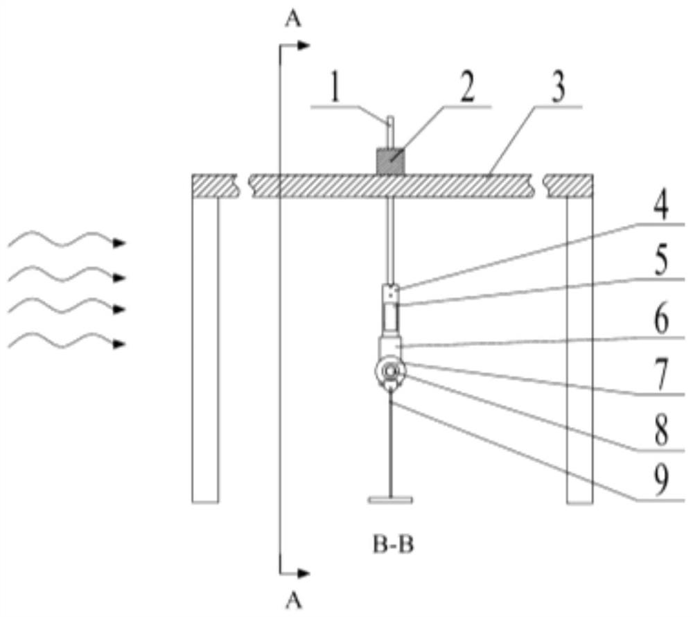
[0032] There is a Ф22 through hole in the vertical direction on the middle position of the beam 2. In the wind blowing direction, at the middle height of the through hole, there are two M8 threaded holes in the front and back, which communicate with the through hole. The connecting rod 1 is inserted into the Ф22 through hole. hole, and use two M8 jackscrews to fix it.

[0033] The connecting rod 1 is round steel with a diameter of Ф20mm, and the total length is 550mm. Cut 10mm toward the center of the circle at the lower end of the connecting rod 1, and the cutting length is 35mm. There are two M5 threaded holes on this length, and two M5 bolts are used to fix the cantilever beam 4. The cantilever beam 4 is a copper sheet with a thickness of 0.6m. . One side of the cantilever beam 4 is glued with the piezoelectric fiber sheet 5 with AB high-performance two-component epoxy resin. The lower part of the cantilever beam 4 is fixed in the end mass 6 with a slot of 0.8 mm wide and...


PUM


Abstract

The invention discloses a piezoelectric hybrid electromagnetic energy collector testing device. The testing device comprises a wind tunnel, a cross beam traverses the top of the wind tunnel, the crossbeam is connected with a cantilever beam through a connecting rod, and the cantilever beam is located in the wind tunnel. A piezoelectric fiber sheet is adhered to the cantilever beam, and the piezoelectric fiber sheet is electrically connected with an external load resistor. The end, away from the connecting rod, of the cantilever beam is fixedly connected with an end mass block. Cylindrical magnets are attracted to the two sides of the end mass block. The two cylindrical magnets are opposite to each other, a clamping frame is arranged close to the cylindrical magnets, a coil is arranged atthe end, close to the cylindrical magnets, of the clamping frame, and the coil is electrically connected with the external load resistor. The testing method of the piezoelectric hybrid electromagneticenergy collector testing device solves the problem that in the prior art, vibration of a collector is unstable.

Description

technical field [0001] The invention belongs to the technical field of piezoelectric hybrid electromagnetic energy harvester testing, relates to a piezoelectric hybrid electromagnetic energy harvester testing device, and also relates to a testing method for the piezoelectric hybrid electromagnetic energy harvester testing device. Background technique [0002] In recent years, research in the field of vibration energy harvesting has attracted extensive attention from scholars at home and abroad. The piezoelectric hybrid electromagnetic energy harvester is a device that can convert the wind energy that exists widely in nature and cannot be directly used at present into electrical energy. It can provide electrical energy to microelectronic devices such as MEMS and sensor devices, and has a wide range of application prospects. . Piezoelectric hybrid electromagnetic energy harvesters generally adopt a cantilever beam structure, which can effectively convert vibration energy in t...

Claims


Application Information

Patent Timeline
IPC IPC(8): G01R31/00G01M9/00
CPCG01R31/00G01M9/00Y02E10/72
Inventor 赵道利梁刚刚孙维鹏黄秋红周捷
Owner XIAN UNIV OF TECH
Learn More