
Method for in-situ real-time quantitative diagnosis of fusion device surface wall part corrosion deposition

A real-time quantitative and in-situ technology, applied in the field of plasma measurement, can solve the problems of poor quantitative analysis accuracy, failure to meet the requirements of fusion device for wall diagnosis, difficulty in determining whether corrosion occurs and the depth of corrosion, etc.

Active Publication Date: 2020-11-13
SOUTHWESTERN INST OF PHYSICS
View PDF11 Cites 0 Cited by
  • Summary
  • Abstract
  • Description
  • Claims
  • Application Information

AI Technical Summary

Problems solved by technology

On the one hand, due to the poor accuracy of current in situ LIBS quantitative analysis, which fails to meet the requirements for wall diagnosis of fusion devices, almost all LIBS diagnostic PFCs are qualitative or semi-quantitative.
On the other hand, the principle of LIBS diagnosis is to determine whether the deposition and the thickness of the deposition layer are based on the depth distribution. However, for the net corrosion area, the surface elements are the same as the matrix material elements, and it is difficult to determine whether corrosion occurs and the corrosion depth.
Although it is a potential problem-solving direction to deduce and evaluate the corrosion amount of PFCs based on the deposition amount of PFCs measured by LIBS, this requires firstly to accurately quantify the deposition amount, and secondly to establish a detailed theoretical model combined with the fusion plasma configuration, and The amount of corrosion can only be obtained by calibrating the theoretical model with enough experimental data, but the current experimental results in this area are very limited

Method used


Image

  • Method for in-situ real-time quantitative diagnosis of fusion device surface wall part corrosion deposition
  • Method for in-situ real-time quantitative diagnosis of fusion device surface wall part corrosion deposition
  • Method for in-situ real-time quantitative diagnosis of fusion device surface wall part corrosion deposition

Examples


Embodiment Construction

[0058] The present invention will be further described below by means of the accompanying drawings and specific embodiments.

[0059] The method is described in the following steps.

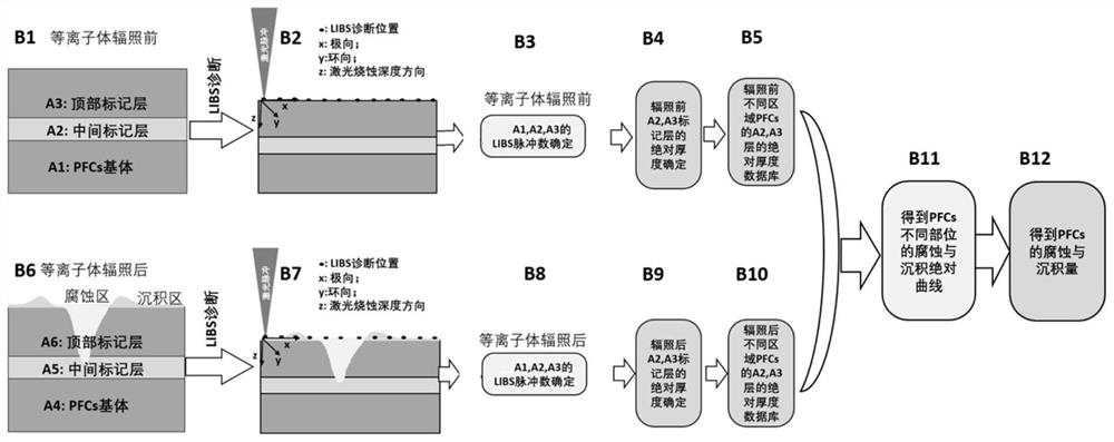
[0060] B1) Fixed placement of multilayer PFCs before plasma irradiation.

[0061] The multilayer PFCs include PFCs substrate A1 at the bottom, middle marking layer A2, and top marking layer A3. The specific positional relationship of A1, A2, and A3 is that A1 is located at the bottom, A2 is located above A1, A3 is located above A2, and the three layers are closely connected.

[0062] The material of the substrate A1 is the same as that of the main body wall of the fusion device, the material of the middle marking layer A2 must be different from A1 and A3, and the material of the top marking layer A3 can be any other material except the middle marking layer A2, which can be determined according to the research task, such as research For the etching and deposition of the tungsten wall, the top ma...


PUM


Abstract

The invention relates to a fusion device plasma measurement technology, in particular to a method for in-situ real-time quantitative diagnosis of fusion device surface wall part corrosion deposition.The method comprises the following steps: firstly, a multilayer film PFCs before plasma irradiation is prepared; afterwards, LIBS spectra are acquired, the LIBS laser pulse number and the absolute thickness of the marking layer are determined, after the multilayer film PFCs are irradiated, the LIBS spectrum of the multilayer film PFCs is collected again, the LIBS laser pulse number and the absolute thickness of the marking layer are determined, the absolute thickness change of the marking layer before and after irradiation is obtained, and the absolute quality of PFCs corrosion and depositionis obtained through integral solving. According to the method, the thickness change of the surface wall part of the multilayer film divertor before and after fusion plasma irradiation is deeply distinguished and measured, and the corrosion and deposition amount of the PFCs is absolutely and quantitatively diagnosed, so that the in-situ and real-time diagnosis and monitoring of the corrosion and deposition of the PFCs are realized.

Description

technical field [0001] The invention belongs to the plasma measurement technology of a fusion device, in particular to an in-situ and real-time diagnosis method for corrosion and deposition of PFCs, a wall part of a fusion device. Background technique [0002] During the operation of the fusion device, the Plasma Facing Components (PFCs) are constantly subjected to complex effects such as bombardment of various particles from the plasma, high thermal load deposition, transient high energy impact, and electromagnetic radiation and electromagnetic force. This will not only cause the radiation effect and damage of the material, lead to the generation, migration and aggregation of defects, and cause the deterioration of the surface and substrate, but also complex phenomena such as backscattering, desorption, physical sputtering, chemical corrosion, and structural damage. Especially for the PFCs in the divertor area of ​​the fusion device, the fusion plasma entering the boundary ...

Claims


Application Information

Patent Timeline
Patent Type & Authority Applications(China)
IPC IPC(8): G01N1/28G01N21/71
CPCG01N1/28G01N21/718
Inventor 赵栋烨才来中胡万鹏黄向玫王亚磊曾晓晓马会聪
Owner SOUTHWESTERN INST OF PHYSICS
Learn More