A connection structure between a water pump shaft and a motor shaft
A connection structure and motor shaft technology, applied in the direction of rigid shaft couplings, pumps, couplings, etc., can solve the problem of unstable connection between the pump shaft and the motor shaft of the pump, achieve easy disassembly, convenient operation, and ensure normal operation Effect
- Summary
- Abstract
- Description
- Claims
- Application Information
AI Technical Summary
Problems solved by technology
Method used
Image
Examples
Embodiment 1
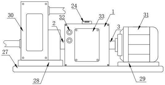
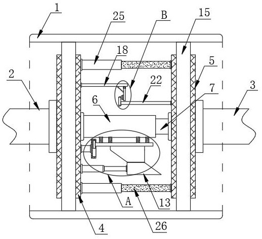
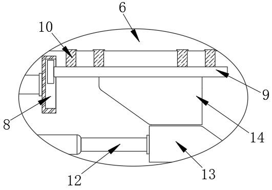
[0027] Refer Figure 1-4 Connection structure of a water pump shaft and the motor shaft, comprising a connection box 1, the water pump shaft 2 and motor shaft 3, one end of the pump shaft 2 is fixedly mounted a first interlock plate 4, one end of the motor shaft 3 is fixedly mounted second linkage plate 5, a first side surface of the middle linkage 4 is attached to a fixed plate fixed to the sleeve 6, the middle plate 5 is fixedly connected to a second side surface of a fixed linkage rod 7 used in the fixed sleeve 6 cooperate, second linkage plate the fixed side of the sleeve 5 and a lower chute plate 6 by the connector block 8 is fixedly mounted, and the inside of the crank plate 8 is slidably connected to the slider 9, fixed to the top of the slide plate 9 is attached to levers 10, 10 of the levers 6 and through the top of the fixed sleeve fixed to the inner sleeve 6 extends, the fixing bar 7 defines a lower surface 10 cooperating with the levers 11 using the slot, a first interl...
Embodiment 2
[0029] Refer figure 2 Sum 5 As another preferred embodiment of the present invention, the difference of Example 1 in that the left and right sides of the connection box 1 are respectively fixedly mounted with a lumen using the first linkage and the second linkage 4 disc tray 5 mating bearing 15, bearing 15 and an inner wall fixedly mounted a plurality of stopper blocks 16, the first linkage surface of the disc tray 4 and 5 are the second linkage defines limiting groove 16 cooperating with a stopper 17 used.
Embodiment 3
[0031] Refer figure 2 Sum 6 As another preferred embodiment of the present invention, the difference of Example 1 in that the first link plate at the lower side 4 of first rail 18 and the upper portion of the stationary sleeve 6 is fixedly mounted, a first surface of the crossbar 18 used side rotational member is connected to the rotary plate 19, a lower portion of the rotating plate 19 is fixedly mounted on one side of an alarm button 20, a side plate 19 is rotated and positioned at an upper portion of the alarm button 21 is fixedly mounted a spring 20, and spring 21 One end of the first surface of the rail 18 is fixedly connected.
PUM
 Abstract
Description
Claims
Application Information
 - R&D Engineer
- R&D Manager
- IP Professional
- Industry Leading Data Capabilities
- Powerful AI technology
- Patent DNA Extraction
Browse by: Latest US Patents, China's latest patents, Technical Efficacy Thesaurus, Application Domain, Technology Topic, Popular Technical Reports.
© 2024 PatSnap. All rights reserved.Legal|Privacy policy|Modern Slavery Act Transparency Statement|Sitemap|About US| Contact US: help@patsnap.com


