
Lifting device for double-coordinate winding manipulator

A lifting device and manipulator technology, applied in the direction of lifting devices, lifting frames, mechanical equipment, etc., can solve the problems of low product quality consistency, low product production efficiency, large labor force, etc., to improve transmission accuracy and motion stability, Avoid equipment damage and ensure stability

Active Publication Date: 2020-11-13
HEFEI PHILEX ELECTRONICS TECH
View PDF8 Cites 5 Cited by
  • Summary
  • Abstract
  • Description
  • Claims
  • Application Information

AI Technical Summary

Problems solved by technology

[0002] Electronic transformers are very important electronic components for safety regulations. During the design and production of their products, parts such as wall tape, bushing, and anti-folding tape will be used to increase the safety characteristics of the transformer. The increase of these parts requires that the transformer can only use Only manual work can meet the safety regulations. As a result, the current safety electronic transformers are mainly operated by manual single-machine operation. The operation method is: the front-line employees manually operate a single-axis winding machine, and the manual winding, tape wrapping, and wrapping retaining wall are relatively low. , wearing sleeves, pasting anti-folding tape, etc., resulting in low production efficiency, large labor demand, and low product quality consistency

Method used


Image

  • Lifting device for double-coordinate winding manipulator
  • Lifting device for double-coordinate winding manipulator
  • Lifting device for double-coordinate winding manipulator

Examples


Embodiment Construction

[0025] The following will clearly and completely describe the technical solutions in the embodiments of the present invention with reference to the accompanying drawings in the embodiments of the present invention. Obviously, the described embodiments are only some, not all, embodiments of the present invention. Based on the embodiments of the present invention, all other embodiments obtained by persons of ordinary skill in the art without creative efforts fall within the protection scope of the present invention.

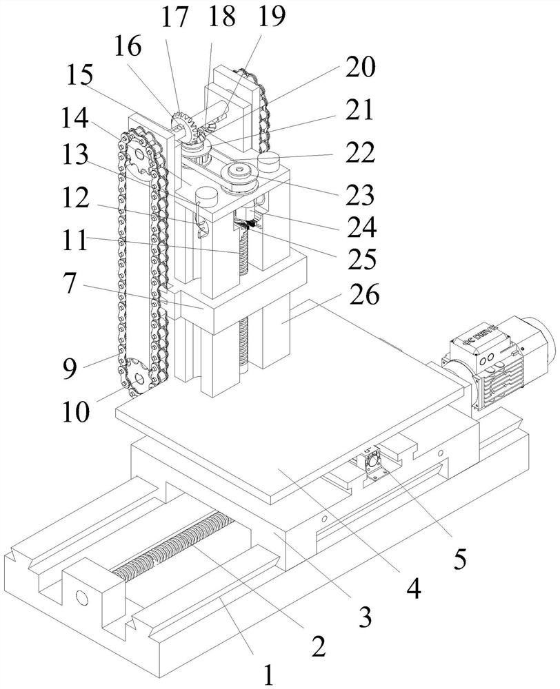
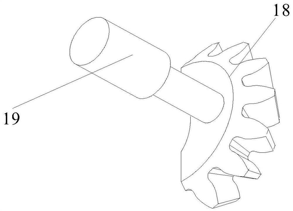
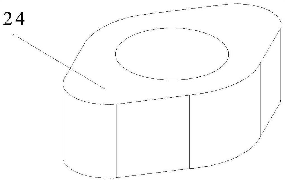
[0026] see Figure 1~5 , in an embodiment of the present invention, a lifting device for a dual-coordinate winding manipulator includes a support platform 4, the support platform 4 is provided with a support 7 that slides up and down in the vertical direction, and the top of the support platform 4 is provided with Support arm 26, the two sides of described support arm 26 are provided with U-shaped chute, and the center of support arm 26 is provided with rectangular...


PUM


Abstract

The invention discloses a lifting device for a double-coordinate winding manipulator, and relates to the technical field of transformer winding equipment. The lifting device for the double-coordinatewinding manipulator comprises a support platform, wherein a support seat sliding up and down in the vertical direction is arranged on the support platform, a support arm is arranged at the top of thesupport platform, U-shaped slide grooves are formed in the two sides of the support arm, a rectangular through groove is formed in the middle of the support arm, the support seat is slidably connectedwith the support arm, and a U-shaped block installed with each U-shaped groove of the support arm in a matching manner is arranged on the support seat; the support seat is in threaded connection witha rotating second lead screw, and the bottom end of the second lead screw is rotationally connected with the support platform; and racks are symmetrically distributed at the two sides close to the U-shaped grooves of the support arm, of the support seat, the racks are connected with a chain in a clamping manner, that is, the racks are embedded into tooth holes of the chain, the chain is connectedwith a rotating chain wheel in a matching manner, and the support seat is controlled to slide up and down through the chain and the second lead screw, so that the transmission accuracy of the supportseat is increased, and the movement stability of the support seat is improved; and meanwhile, the support seat has loading capacity to a certain extent, so that the winding stability of the manipulator is ensured.

Description

technical field [0001] The invention belongs to the technical field of transformer winding equipment, and in particular relates to a lifting device for a dual-coordinate winding manipulator. Background technique [0002] Electronic transformers are very important electronic components for safety regulations. During the design and production of their products, parts such as wall tapes, bushings, and anti-folding tapes will be used to increase the safety characteristics of the transformer. The increase of these parts requires that the transformer can only use Only manual work can meet the safety regulations. As a result, current safety electronic transformers are mainly operated by manual stand-alone. , wearing sleeves, pasting reflex tape, etc., resulting in low product production efficiency, large labor demand, and low product quality consistency. [0003] In order to improve production efficiency and reduce production costs, a special winding manipulator is designed and de...

Claims


Application Information

Patent Timeline
Patent Type & Authority Applications(China)
IPC IPC(8): B66F7/00B66F7/28F16H57/04H01F41/06
CPCB66F7/025B66F7/28F16H57/0497H01F41/06
Inventor 吴伶俐章立勇吴富荣
Owner HEFEI PHILEX ELECTRONICS TECH
Learn More