Intelligent flaming obstacle clearing unmanned aerial vehicle

A drone and obstacle-clearing technology, applied in the field of drones, can solve the problems of low service life and achieve the effects of improving service life, high strength and reducing bearing pressure

Active Publication Date: 2020-11-13
CHONGQING COLLEGE OF ELECTRONICS ENG
View PDF9 Cites 1 Cited by
  • Summary
  • Abstract
  • Description
  • Claims
  • Application Information

AI Technical Summary

Problems solved by technology

[0005] The present invention intends to provide an intelligent fire-sprayi

Method used


Image

  • Intelligent flaming obstacle clearing unmanned aerial vehicle

Examples


Embodiment 1

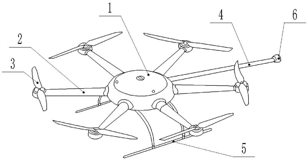
[0035] Such as figure 1 As shown, an intelligent fire-breathing obstacle-clearing UAV includes a power unit and a fire-breathing device fixed on the side wall of the fuselage 1, wherein the power unit is detachably connected to the side wall of the fuselage 1, and the fire-breathing device is connected to the side wall of the machine. The body 1 is bonded and fixed; the material of the body 1 is PA66+30GF (nylon 66 plus 30% glass fiber material), and its shape is a vertical column structure with a hollow interior;

[0036] There are multiple power devices, and each power device includes a bracket 2, one end of the bracket 2 is fixedly connected to the side wall of the fuselage 1, specifically, the shape of the bracket 2 is a hollow cylindrical structure (hollow cylinder), and the material of the bracket is the same PA66+30GF is used; and the end of the bracket 2 close to the side wall of the fuselage 1 is drilled with an external thread, and correspondingly, the side wall of t...

Embodiment 2

[0042] Compared with Embodiment 1, the only difference is that a booster pump is also fixed between the fuel tank and the fuel rod, that is, the input end of the booster pump is fixedly connected with the fuel delivery pipe of the fuel tank, and the output end of the pump is connected to one end of the fuel rod. The fixed connection can use the booster pump to continuously output the fuel in the fuel tank to the fuel rod.

Embodiment 3

[0044] Compared with Embodiment 1, the only difference is that a stall detection device is bonded to the bottom end of the fuel rod, and the stall detection device adopts a closed box body; it also includes a slider located at the left end of the bottom of the box body, the slider and the box body The bottom of the box body is slidingly connected; the right end of the bottom of the box body is bonded with an induction switch; in addition, for the power device of the drone, the bottom of the bracket and the installation groove are flush, and the bottom of each bracket in this embodiment is welded with a storage Gas tank; also includes air guide pipe and cylinder fixed at the bottom of each installation groove, the cylinder and the gas storage tank are communicated through the air guide pipe; the metal baffle plate for blocking the flow of gas is arranged in the air guide pipe, and the bottom end of each bracket is also The electromagnet is bonded, and the electromagnet is locate...


PUM


Abstract

The invention relates to the technical field of unmanned aerial vehicles, and in particular relates to an intelligent flaming obstacle clearing unmanned aerial vehicle which comprises a vehicle body,power devices and a flaming device, the vehicle body is of a vertically-arranged hollow cylinder structure, and the power devices and the flaming device are fixed to the side wall of the vehicle body.The number of the power devices is multiple, each power device comprises a support, one end of each support is fixedly connected with the side wall of the vehicle body, a mounting groove is fixed tothe other end of each support, a motor is fixed in each mounting groove, and a paddle is fixed to the output end of each motor; the flaming device comprises an oil tank, a fuel rod, an igniter and a nozzle, the oil tank is fixed in the vehicle body, and the nozzle is connected with the oil tank through the fuel rod; the igniter is fixed at the nozzle; the intelligent flaming obstacle clearing unmanned aerial vehicle further comprises a first undercarriage device and a second undercarriage device which are positioned at the lower end of the vehicle body; by adopting the scheme, the problem of short service life of the unmanned aerial vehicle can be solved.

Description

technical field [0001] The invention relates to the technical field of unmanned aerial vehicles, in particular to an intelligent fire-breathing obstacle-clearing unmanned aerial vehicle. Background technique [0002] Power line faults caused by foreign matter connection and discharge on high-voltage lines seriously affect the safe operation of the power grid and the reliable use of electricity in society. For the problem of foreign matter on high-voltage lines, the traditional solution is to manually climb to the high-voltage line for obstacle removal operations, but manual obstacle removal consumes a lot of manpower and material resources, and safety is difficult to guarantee. Moreover, this method of power failure maintenance or live work is not only dangerous, but also has low work efficiency, and it will also affect the reliable operation of the power grid and the normal electricity consumption of the society. There are also some line-clearing robots that use the fricti...

Claims


Application Information

Patent Timeline
IPC IPC(8): B64C39/02B64C1/00B64C11/16B64C25/62B64C25/64H02G1/02
CPCB64C39/02B64C1/00B64C11/16B64C25/62B64C25/64H02G1/02B64C2001/0072B64U10/10B64U2101/00
Inventor 陈世江任勇马泽仁曾俊超廖正平周胡阳杨江熊佳豪
Owner CHONGQING COLLEGE OF ELECTRONICS ENG
Why Eureka
Try Eureka