Non-transmission type automatic reversing structure based on machinery

A non-transmission, automatic commutation technology, applied in the field of mechanical transmission, can solve the problems of slow commutation speed and unfavorable rapid commutation, and achieve the effect of simple adjustment and stable transmission position.

Active Publication Date: 2020-11-10
浙江昂科工程技术有限公司
View PDF12 Cites 0 Cited by
  • Summary
  • Abstract
  • Description
  • Claims
  • Application Information

AI Technical Summary

Problems solved by technology

[0006] The purpose of the present invention is to provide a non-transmission automatic reversing structure based on machinery to solve the problem that the currently used rotating shaft reversing proposed in the above background technology mainly uses a contactor to control the steering of a three-phase motor to convert the direction of rotation. The speed is slow, which is not conducive to fast reversing, and it is impossible to realize the problem of fast reversing of the transmission system during the mechanical operation.

Method used


Image

  • Non-transmission type automatic reversing structure based on machinery
  • Non-transmission type automatic reversing structure based on machinery
  • Non-transmission type automatic reversing structure based on machinery

Examples


Embodiment Construction

[0030] Next, the technical solutions in the embodiments of the present invention will be described in connection with the drawings of the embodiments of the present invention, and it is understood that the described embodiments are merely the embodiments of the present invention, not all of the embodiments.

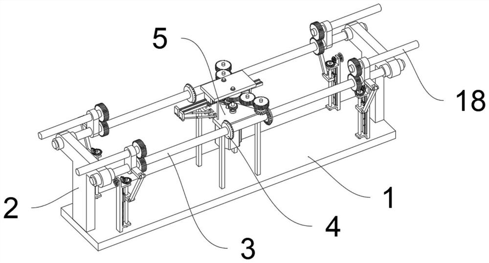
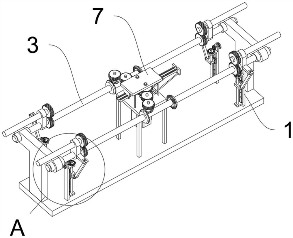
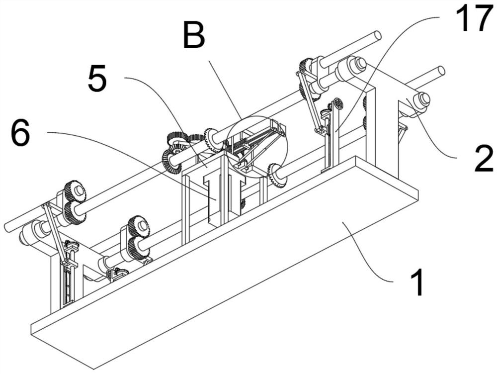
[0031] See Figure 1 to 8One embodiment of the present invention is: a mechanical non-conductive automatic automatic commutation structure, including a base 1; two sides of the top of the base 1 are fixedly provided with two sets of driven housing 2; driven bobbin 2 For the T-shaped structure, the two sets of two sets of slave axes 2 are rotated between the two sets of driven shafts 3; the outer side of the driven shaft 3 is fixedly provided with two sets of reversing gear 4, and the reunion gear 4 All of the cone gears, the same side reversing gear 4 tooth surface is opposite; the top of the base 1 is fixed to the frame 5; the intermediate bottom portion of the frame 5 is fix...


PUM


Abstract

The invention discloses a non-transmission type automatic reversing structure based on machinery, relates to the technical field of mechanical transmission, and solves the problems of low reversing speed and difficulty in quick reversing due to the fact that a contactor is mainly used for controlling the rotation direction of a three-phase motor to switch the rotation direction in the conventionalrotating shaft reversing process. The non-transmission type automatic reversing structure based on machinery comprises a base. Two driven shaft frames are fixedly arranged on the two sides of the topof the base. The driven shaft frames are each of a T-shaped structure, and two driven shafts are rotationally arranged between the two sides of the tops of the two driven shaft frames. Two sets of reversing gears are fixedly arranged on the outer side of each driven shaft, the reversing gears are bevel gears, the tooth surfaces of the reversing gears on the same side are opposite, a quick reversing function is provided for the reversing shaft brackets by arranging a reversing shaft bracket and a sliding rack, and the hydraulic cylinder is used for driving the sliding rack to move, so the angle of the reversing shaft bracket can be adjusted by meshing the sliding rack with the tooth-shaped structure of the reversing shaft bracket.

Description

Technical field [0001] The present invention relates to the field of mechanical transmission technologies, and is specifically a mechanical non-driving automatic automatic commutation structure. Background technique [0002] The shaft is a cylindrical article in the middle of the bearing or in the middle of the wheel or in the middle of the wheel, but there are also fewer partial. The shaft is a mechanical part that is supported by rotating the part and swiring to transmit moving, torque or bending moments, is also the mainly used drive mode. [0003] A patented, for example, a patent number CN207677590U discloses a structure for positioning the commutator and the rotating shaft, including a shaft, a core, a commutator body, the core, and a winding, the iron core. On the side, a connecting sleeve is provided, and the connection sleeve is provided with a commutator body, the rotating shaft through the core, a connection sleeve, and a commutator body, and the interior of the connec...

Claims


Application Information

Patent Timeline
Patent Type & Authority Applications(China)
IPC IPC(8): H02P1/40H02K7/116H02K7/06
CPCH02K7/06H02K7/116H02K7/1163H02P1/40
Inventor 张宇洋
Owner 浙江昂科工程技术有限公司
Why Eureka
Try Eureka