
Turbine rotor with cooling, air-entraining and pressurizing impeller

A technology for turbine rotors and impellers, applied in the direction of blade support components, engine components, machines/engines, etc., can solve the problems of large space, complex structure, and large number of parts, and achieve simple structure, improved cooling effect, and high reliability Effect

Pending Publication Date: 2020-11-10
AECC SHENYANG ENGINE RES INST
View PDF5 Cites 6 Cited by
  • Summary
  • Abstract
  • Description
  • Claims
  • Application Information

AI Technical Summary

Problems solved by technology

The existing turbine rotor structure requires a large space, complex structure, and a large number of parts; the existing turbine disc rim and blade cooling cooling air pressure will not increase

Method used


Image

  • Turbine rotor with cooling, air-entraining and pressurizing impeller
  • Turbine rotor with cooling, air-entraining and pressurizing impeller

Examples


Embodiment Construction

[0021] In order to make the purpose, technical solution and advantages of the application more clear, the technical solution in the embodiment of the application will be described in more detail below in conjunction with the drawings in the embodiment of the application. In the drawings, the same or similar reference numerals denote the same or similar elements or elements having the same or similar functions throughout. The described embodiments are some, but not all, embodiments of the application. The embodiments described below by referring to the figures are exemplary, and are intended to explain the present application, and should not be construed as limiting the present application. Based on the embodiments in this application, all other embodiments obtained by persons of ordinary skill in the art without creative efforts fall within the protection scope of this application. Embodiments of the present application will be described in detail below in conjunction with th...


PUM


Abstract

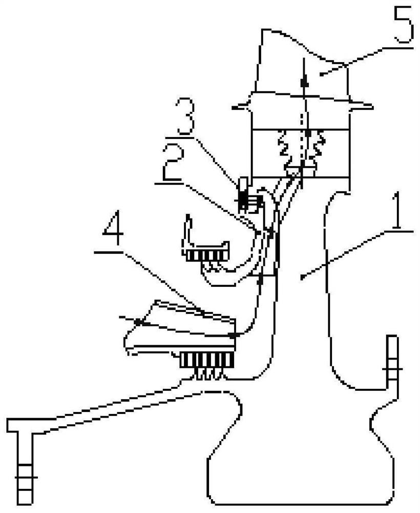
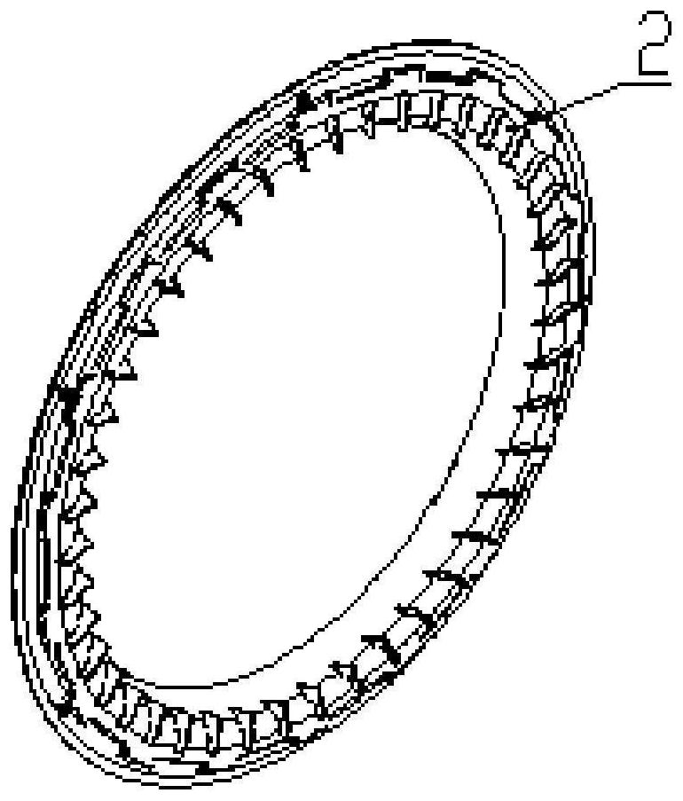
The invention belongs to the technical field of aero-engines, and particularly relates to a turbine rotor with a cooling, air-entraining and pressurizing impeller. The turbine rotor comprises a turbine disc, a sealing disc and a prewhirl device; the turbine disc sequentially comprises a disc hub, a web and a disc edge outwards in the radial direction, wherein first comb teeth and a drum are integrally formed on the front side of the first end of the web, and a first cooling channel communicating with a mortise of the disc edge is formed in the second end of the web; the sealing disc is arranged on the front side of the second end of the turbine disc web, second comb teeth on the front side of the sealing disc are connected with a first honeycomb structure in a matched mode, a centrifugal pressurizing impeller is arranged on the rear side, and a second cooling air channel communicating with a first cooling air channel is formed in the centrifugal pressurizing impeller; and the rear sideof the prewhirl device is connected with the first comb teeth in a matched mode through a second honeycomb structure, and a third cooling channel communicating with the second cooling air channel isformed in the prewhirl device. The turbine rotor has the advantages of being simple in structure, high in reliability, small in overall dimension, light in weight and capable of effectively increasingthe pressure of cooling air and improving the cooling effect of the turbine disc rim and a blade.

Description

technical field [0001] The application belongs to the technical field of aero-engines, and in particular relates to a turbine rotor with a cooling bleed air booster impeller. Background technique [0002] As an important part of an aero-engine, the turbine rotor has been in a high-speed, high-load and high-temperature working environment for a long time, under the combined action of thermal load and mechanical load, and is prone to various forms of failure and damage, which is harmful to the safe flight of the aircraft. It poses a great threat, so high reliability and cooling performance are the guarantee for the normal operation of the turbine rotor. [0003] In the traditional turbine rotor structure, the turbine disc, grate disc and drum shaft are connected by bolts, which is suitable for the design of high-power turbine with large space and complex structure. The conventional cooling method of the turbine disk rim and blades is that the cooling gas directly cools the tu...

Claims


Application Information

Patent Timeline
Patent Type & Authority Applications(China)
IPC IPC(8): F01D5/08F01D5/06
CPCF01D5/08F01D5/081F01D5/06
Inventor 徐倩马增祥杨养花姜宁
Owner AECC SHENYANG ENGINE RES INST
Learn More