Environment-friendly industrial sewage treatment device

A sewage treatment device, environmentally friendly technology, applied in mixers with rotary stirring devices, transportation and packaging, chemical/physical processes, etc. , to achieve the effect of easy storage

Pending Publication Date: 2020-11-10
陈士磊
View PDF8 Cites 1 Cited by
  • Summary
  • Abstract
  • Description
  • Claims
  • Application Information

AI Technical Summary

Problems solved by technology

If the waste water is discharged without treatment, it will cause different properties and degrees of pollution to the water body, thereby endangering human health and affecting industrial and agricultural production.
[0003] With the increase of environmentally friendly industrial sewage treatment devices, the problem of industrial sewage discharge is becoming more and more serious. Many factories discharge sewage directly into the river, which will cause harm to animals and organisms in the water and affect the ecological balance. Although the relevant departments are conducting investigations, with the increase of environmentally friendly industrial sewage treatment devices, there are more small factories that are not easy to be found. The industrial sewage that fails to meet the standard is directly discharged into the river. For these sewage, Generally, it is transported to the water treatment plant for treatment, and the transportation is cumbersome. If the industrial sewage flows to the surface of the river bank, it will affect the surface soil and cause harm to plants. Therefore, research and design an environmentally friendly Sewage treatment device to solve the problem of difficult industrial sewage treatment

Method used


Image

  • Environment-friendly industrial sewage treatment device
  • Environment-friendly industrial sewage treatment device
  • Environment-friendly industrial sewage treatment device

Examples


Embodiment Construction

[0019] The following will clearly and completely describe the technical solutions in the embodiments of the present invention with reference to the accompanying drawings in the embodiments of the present invention. Obviously, the described embodiments are only some, not all, embodiments of the present invention. Based on the embodiments of the present invention, all other embodiments obtained by persons of ordinary skill in the art without making creative efforts belong to the protection scope of the present invention.

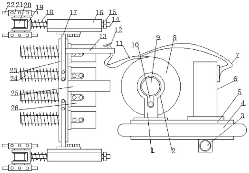
[0020] see Figure 1-4 , the present invention provides a technical solution:

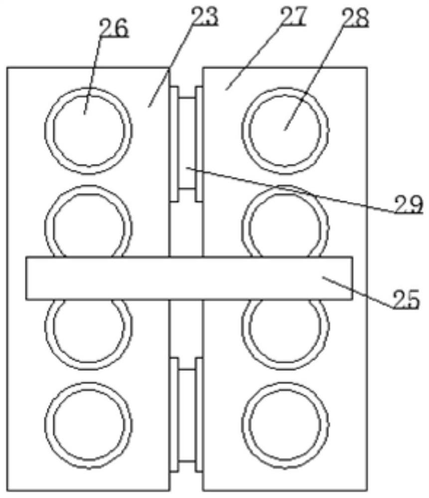
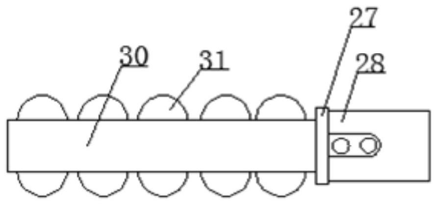
[0021] An environment-friendly sewage treatment device, comprising a first connection plate 23, a second connection plate 27 and a placement plate 5, the bottom surface of the placement plate 5 is equipped with a liquid inlet pipe 3, and the outside of the placement plate 5 is set with a floating plate 4, The right side of the upper surface of the placement plate 5 is fixedly equi...


PUM


Abstract

In order to solve the problem that industrial sewage is difficult to treat in the prior art, the invention discloses an environment-friendly industrial sewage treatment device. The environment-friendly industrial sewage treatment device comprises a first connecting plate, a second connecting plate and a placing plate, wherein a liquid inlet pipe is arranged on the bottom surface of the placing plate, and a floating plate is arranged on the outer side of the placing plate in a sleeving manner; a water pump is fixedly mounted on the right side of the upper surface of the placing plate, a guide pipe is mounted at the water outlet end of the water pump, a supporting frame is fixedly mounted on the left side of the upper surface of the placing plate, a lantern ring is welded to the top end of the supporting frame, a first motor is mounted in front of the lantern ring, and a machine frame is fixedly mounted between the first motor and the supporting frame; and a rotating disc is mounted behind the first motor, a liquid outlet pipe is wound around the rotating disc, and inflation holes are uniformly formed in the liquid outlet pipe. Through cooperation of second motors and third motors, the industrial sewage can permeate into the ground more easily through hole drilling and hole collapsing manners and mixing of the industrial sewage with soil, and treatment of the industrial sewage isachieved through a covering method.

Description

technical field [0001] The invention relates to the field of sewage treatment, in particular to an environment-friendly sewage treatment device. Background technique [0002] Pure water changes its original physical or chemical properties after use, and becomes wastewater containing different types of impurities. Industrial wastewater is wastewater such as process wastewater, cooling water, waste gas washing water, equipment and site washing water discharged in industrial production. If the waste water is discharged without treatment, it will cause different properties and different degrees of pollution of the water body, thereby endangering human health and affecting industrial and agricultural production. [0003] With the increase of environmentally friendly industrial sewage treatment devices, the problem of industrial sewage discharge is becoming more and more serious. Many factories discharge sewage directly into the river, which will cause harm to animals and organis...

Claims


Application Information

Patent Timeline
Patent Type & Authority Applications(China)
IPC IPC(8): E21B3/02E21B17/22E21B7/00B01F7/02B01F3/12
CPCE21B3/02E21B17/22E21B7/00B01F23/53B01F27/2322B01F27/60
Inventor 陈士磊
Owner 陈士磊
Why Eureka
Try Eureka