


Quick Research
Generate reliable direction feasibility study reports for your R&D in just a few steps.

Technical Q&A
Discover and master advanced knowledge NOW. Basics, ideas, possibilities, all at once.

Find Solutions
As an expert in R&D theories, this can generate solutions to your technical problems instantly.

Evaluate Feasibility
Analyze your overall solution with one click, know your potential R&D risks in advance.

Monitor Landscape
Get weekly tech updates, stay abreast of the latest tech innovations and key insights.
Polishing device for end surface of circular saw web
A circular saw blade and end face technology, which is applied in the field of circular saw blade end face grinding devices, can solve the problems of insufficient fixation of circular saw blades and affecting the safety of the device
- Summary
- Abstract
- Description
- Claims
- Application Information
AI Technical Summary
Problems solved by technology
Method used
Image

Examples
Embodiment 1
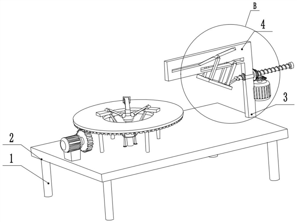
[0027] see Figure 1-6 , a circular saw blade end face grinding device, comprising a workbench 2, the left and right sides of the lower surface of the workbench 2 are provided with support legs 1, the right end of the upper surface of the workbench 2 is provided with a support frame 3, and the top of the support frame 3 is provided with Guide plate 4, the top of described guide plate 4 is provided with first chute 15, and the middle part of first chute 15 is slidingly connected with first guide rod 16, and the front and rear ends of first guide rod 16 are fixedly connected with first connecting rod 17 The upper end of the first connecting rod 17 is fixedly connected to the left side of the grinding head 11, the bottom of the guide plate 4 is provided with a second chute 14, and the middle part of the second chute 14 is slidably connected to the second guide rod 13, and the first slide The left side of the groove 15 is parallel to the workbench 2, the right side of the first ch...
Embodiment 2
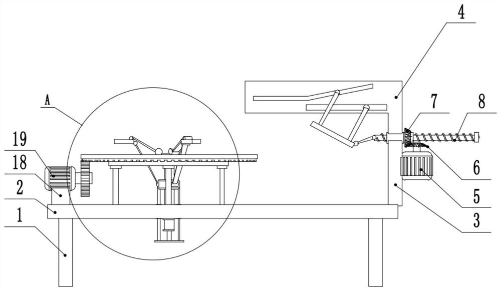
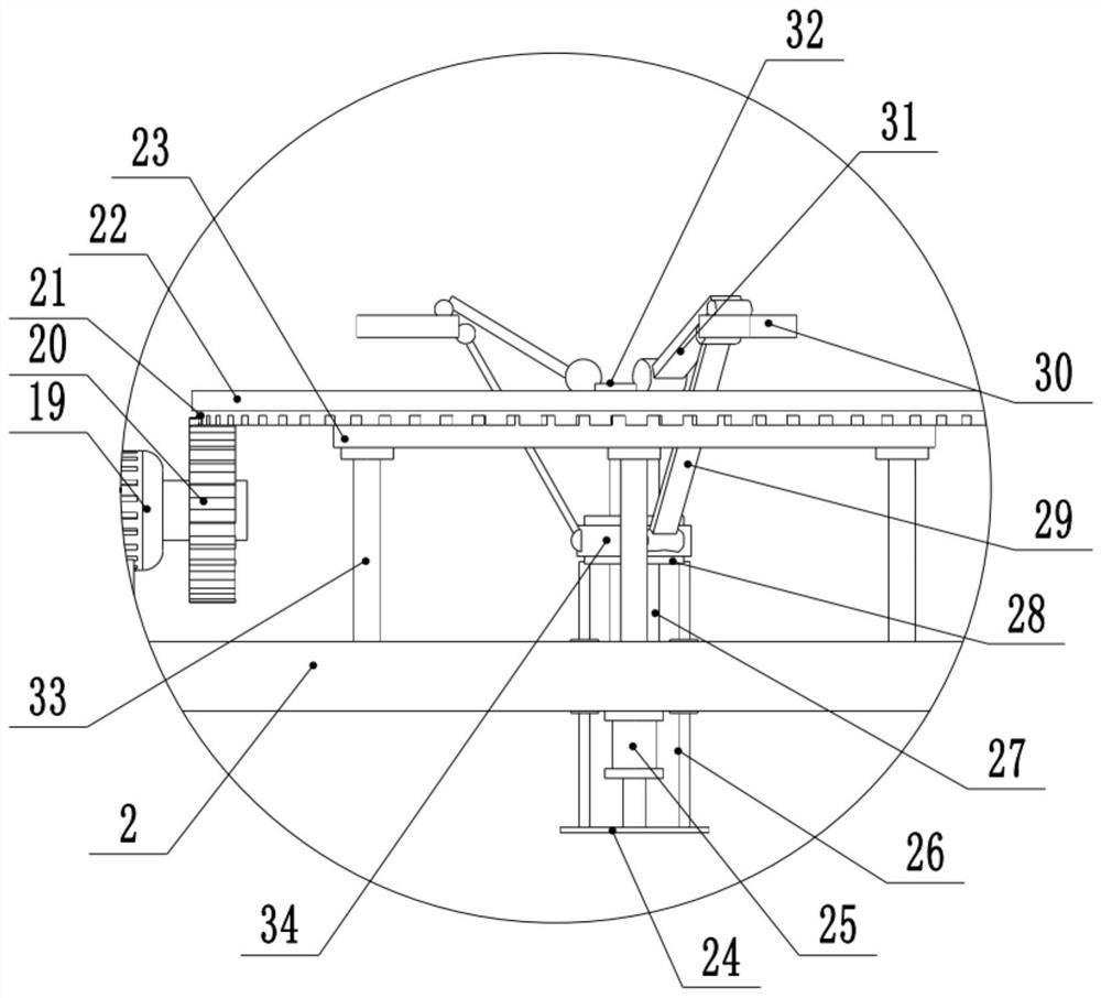
[0030] see figure 2 and image 3 , the other content of this embodiment is the same as that of Embodiment 1, the difference is that: the left side of the upper surface of the workbench 2 is provided with a motor holder 18, and the top of the motor holder 18 is provided with a second drive motor 19, the second The output shafts of the two drive motors 19 are fixedly connected to the driving gear 20 , the top of the driving gear 20 meshes with the left side of the driven gear ring 21 , and the top of the driven gear ring 21 is fixedly connected to the bottom of the turntable 22 . The second driving motor 19 drives the rotating table 22 to rotate through the driving gear 20 and the driven gear ring 21 connected by meshing, so as to drive the circular saw blade to rotate, realize the automatic operation of the device, and reduce manual participation.
[0031]During the implementation of the present invention, the cylinder 25 is started, and the piston rod of the cylinder 25 shri...
PUM
 Abstract
Description
Claims
Application Information
 - R&D Engineer
- R&D Manager
- IP Professional
- Industry Leading Data Capabilities
- Powerful AI technology
- Patent DNA Extraction
Browse by: Latest US Patents, China's latest patents, Technical Efficacy Thesaurus, Application Domain, Technology Topic, Popular Technical Reports.
© 2024 PatSnap. All rights reserved.Legal|Privacy policy|Modern Slavery Act Transparency Statement|Sitemap|About US| Contact US: help@patsnap.com