
Pipe supporting device for laser cutting

A laser cutting and supporting device technology, applied in auxiliary devices, laser welding equipment, welding/cutting auxiliary equipment, etc., can solve the problems of no scale structure, difficult equipment cleaning, low work efficiency, etc., to reduce splashing and improve Operational safety and high work efficiency

Inactive Publication Date: 2020-11-10
合肥德纳达信息科技有限公司
View PDF0 Cites 2 Cited by
  • Summary
  • Abstract
  • Description
  • Claims
  • Application Information

AI Technical Summary

Problems solved by technology

[0004] The object of the present invention is to provide a pipe support device for laser cutting, through the design of the first support ring, the third support ring, the driving gear, the scale and the flushing air pipe, it solves the problem that the existing laser cutting machine cannot realize the pipe fittings Rotate to achieve cutting at various angles. The debris generated by cutting the pipe will splash around, which not only increases the risk, but also is not easy to clean the equipment in the later stage. Problems of low work efficiency and low security

Method used


Image

  • Pipe supporting device for laser cutting
  • Pipe supporting device for laser cutting
  • Pipe supporting device for laser cutting

Examples


Embodiment Construction

[0038] The following will clearly and completely describe the technical solutions in the embodiments of the present invention with reference to the accompanying drawings in the embodiments of the present invention. Obviously, the described embodiments are only some, not all, embodiments of the present invention. Based on the embodiments of the present invention, all other embodiments obtained by persons of ordinary skill in the art without creative efforts fall within the protection scope of the present invention.

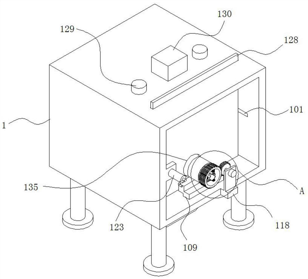
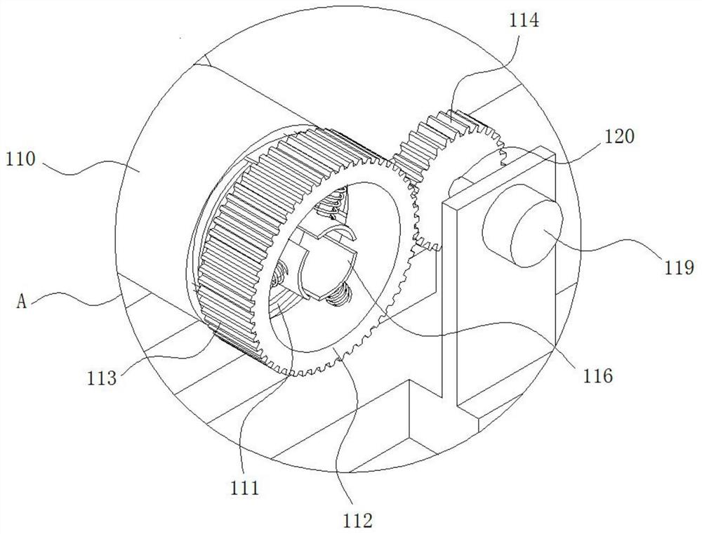
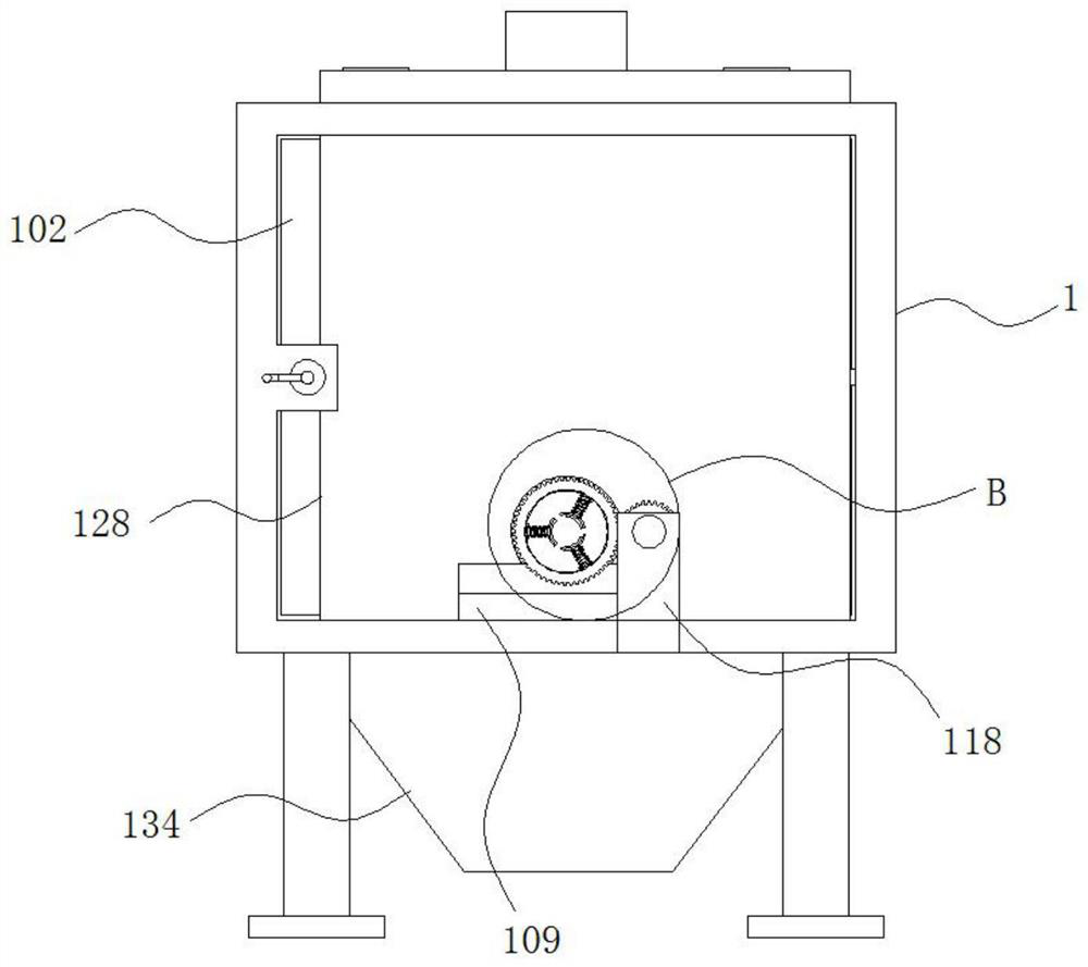
[0039] see Figure 1-12 , the present invention is a pipe support device for laser cutting, including a box 1;

[0040] A chute 101 is provided on the opposite inner surface of the box body 1; the inner wall of the chute 101 is slidably connected with a slide plate 102 through a slider; the side surface of the slide plate 102 is attached to the inner surface of the box body 1;

[0041] One side of the slide plate 102 is fixedly connected with a first support ring ...


PUM


Abstract

The invention discloses a pipe supporting device for laser cutting, and relates to the technical field of pipe cutting. The pipe supporting device comprises a box body; Sliding grooves are formed in the opposite inner side surfaces of the box body; a sliding plates is slidably connected to the inner walls of the sliding grooves through sliding blocks; a first supporting ring is fixedly connected to one side surface of the sliding plate; one end of a first telescopic rod is fixedly connected with a first electromagnet; a second supporting ring is fixedly connected to the top of a supporting table; a third supporting ring is fixedly connected into a second sliding clamping groove through a sliding block; the peripheral side surface of the third supporting ring is fixedly connected with a tooth-shaped structure; one side surface of the tooth-shaped structure is engaged with a driving gear; and one end of the second telescopic rod is fixedly connected with a second electromagnet. Through the design of the first electromagnet, the second sliding clamping groove, the second electromagnet, the driving gear and the tooth-shaped structure, the pipe supporting device can clamp a pipe to rotate by 360 degrees without disassembly for readjustment of the direction of the pipe, and is simple in structure, convenient to operate, high in working efficiency and high in practicability.

Description

technical field [0001] The invention belongs to the technical field of pipe cutting, in particular to a pipe support device for laser cutting. Background technique [0002] Laser cutting is to focus the laser emitted from the laser into a high power density laser beam through the optical path system. The laser beam irradiates the surface of the workpiece to make the workpiece reach the melting point or boiling point, and at the same time, the high-pressure gas coaxial with the beam blows away the molten or vaporized metal. With the movement of the relative position of the beam and the workpiece, the material will eventually form a slit, so as to achieve the purpose of cutting. [0003] Existing laser cutting machines cannot accurately position and clamp pipes of different diameters, and cannot realize 360-degree rotation of the clamped pipes during cutting, so as to realize cutting of pipes at different angles, so the pipes can only be removed and reinstalled , the operati...

Claims


Application Information

Patent Timeline
Patent Type & Authority Applications(China)
IPC IPC(8): B23K26/70B23K26/08B23K26/142B23K37/053B23K26/38B23K101/06
CPCB23K26/0823B23K26/38B23K37/0533B23K26/142B23K26/702B23K2101/06
Inventor 余取铭
Owner 合肥德纳达信息科技有限公司
Learn More