
Transport vehicle fumigation system and method

A technology in transport vehicles and compartments, applied in the field of vehicle fumigation, can solve the problems of reducing the fumigation and disinfection efficiency of vehicles, the inability to achieve all-round fumigation, and increasing the workload of operations, so as to solve the problem of unbalanced space concentration, reduce fumigation costs, The effect of improving efficiency

Pending Publication Date: 2020-11-10
北京安洁康生物科技有限公司
View PDF0 Cites 2 Cited by
  • Summary
  • Abstract
  • Description
  • Claims
  • Application Information

AI Technical Summary

Problems solved by technology

[0002] After the transport vehicles enter the pollution sources, such as feed mills, farms and slaughterhouses, the vehicles often contain a large number of microorganisms and various dirt, and special fumigation and disinfection treatments are required for the vehicles; common vehicle decontamination usually uses One fumigation tube fumigates all sides of the vehicle. When fumigation is performed on different sides of the vehicle, the position of the fumigation tube needs to be changed, which greatly increases the workload of the operation and reduces the efficiency of the fumigation of the vehicle.
[0003] When fumigation and disinfection of vehicles is carried out with complex decontamination devices, fumigation rooms are often used for fumigation. Traditional fumigation rooms only add fumigation gas to the fumigation room. Due to the unevenness of the internal fumigation gas, it is impossible to complete the fumigation of vehicles, including All-round fumigation including the chassis, so that the fumigated transportation vehicles still have a small amount of dirt and microorganisms, which increases the possibility of contamination

Method used


Image

  • Transport vehicle fumigation system and method
  • Transport vehicle fumigation system and method
  • Transport vehicle fumigation system and method

Examples


Embodiment Construction

[0035] In order to make the purpose, technical solutions and advantages of the embodiments of the present invention clearer, the technical solutions in the embodiments of the present invention will be clearly and completely described below in conjunction with the drawings in the embodiments of the present invention. Obviously, the described embodiments It is a part of embodiments of the present invention, but not all embodiments. Based on the embodiments of the present invention, all other embodiments obtained by persons of ordinary skill in the art without making creative efforts belong to the protection scope of the present invention.

[0036] Below in conjunction with accompanying drawing, the present invention is described in further detail:

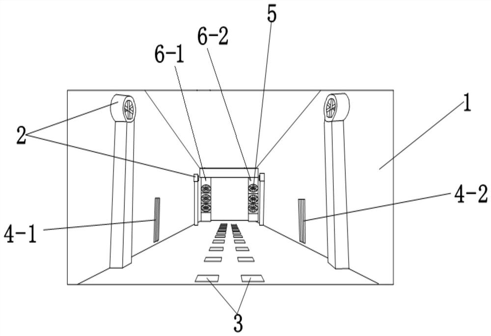
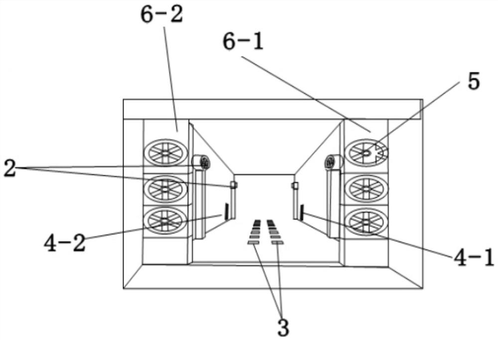
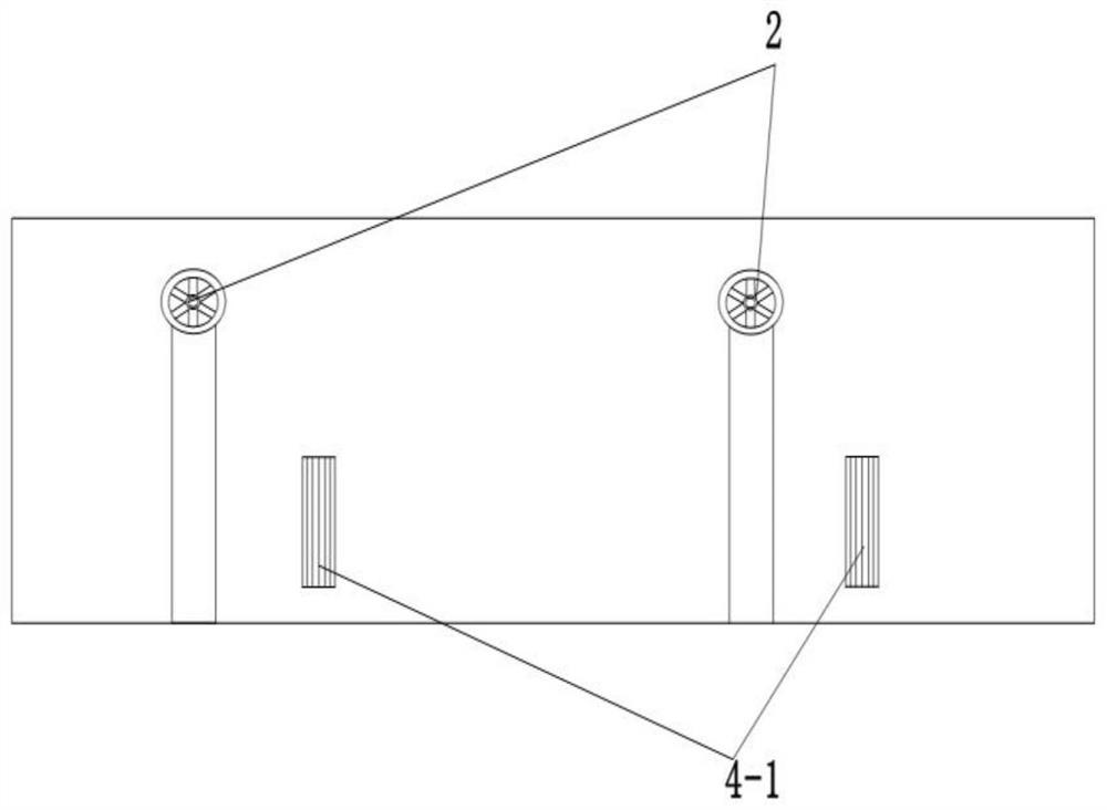
[0037] Such as Figure 1-Figure 5 As shown, the present invention discloses a transportation vehicle fumigation system, which includes a fumigation room 1 and a gas generating device. The gas generation device transports the fumigat...


PUM


Abstract

The invention discloses a transport vehicle fumigation system and method. The transport vehicle fumigation system comprises a fumigation room and a gas generation device, wherein the gas generation device delivers fumigation gas into the fumigation room through a pipeline; a trench circulating device and a carriage inner air circulating device are arranged in the fumigation room; the trench circulating device comprises a plurality of air draft devices and a plurality of bottom air outlet groups; the air draft devices deliver gas in the fumigation room to the bottom air outlet groups through pipelines; the carriage inner air circulating device comprises a movable air blowing device; and the movable air blowing device is arranged at one end of an outlet or an inlet of the fumigation room. Through the trench circulating device and the carriage inner air circulating device, all-around fumigation disinfection of a vehicle is realized, and the fumigation efficiency of the transport vehicle is improved; and through arrangement of the gas generation device, microorganisms in air and on the surface of the vehicle can be effectively killed, and meanwhile, corrosion to equipment and the vehicle is also reduced.

Description

technical field [0001] The invention relates to the field of vehicle fumigation, in particular to a transport vehicle fumigation system and a fumigation method. Background technique [0002] After the transport vehicles enter the pollution sources, such as feed mills, farms and slaughterhouses, the vehicles often contain a large number of microorganisms and various dirt, and special fumigation and disinfection treatments are required for the vehicles; common vehicle decontamination usually uses One fumigation tube fumigates all sides of the vehicle. When fumigation is performed on different sides of the vehicle, the position of the fumigation tube needs to be changed, which greatly increases the workload of the operation and reduces the efficiency of the fumigation of the vehicle. . [0003] When fumigation and disinfection of vehicles is carried out with complex decontamination devices, fumigation rooms are often used for fumigation. Traditional fumigation rooms only add f...

Claims


Application Information

Patent Timeline
Patent Type & Authority Applications(China)
IPC IPC(8): A61L2/20A61L2/24A61L2/26A61L9/015A61L101/10A61L101/06
CPCA61L2/20A61L2/202A61L2/24A61L2/26A61L9/015A61L2202/14A61L2209/11A61L2209/212A61L2209/21
Inventor 凡占胜米越王臣杜明辉
Owner 北京安洁康生物科技有限公司
Learn More