
A remote temperature measuring device

A temperature measuring device, long-distance technology, applied in the direction of measuring devices, electric devices, thermometers, etc., can solve the problems of signal amplitude attenuation, affecting the accuracy of the test system, and being susceptible to electromagnetic interference

Active Publication Date: 2012-08-29
NAVAL UNIV OF ENG PLA
View PDF0 Cites 2 Cited by
  • Summary
  • Abstract
  • Description
  • Claims
  • Application Information

AI Technical Summary

Problems solved by technology

[0006] During the field test, it was found that for those voltage output temperature sensors, once the measured body (including the sensor head) is far away from the subsequent processing circuit (board), such as more than 20 meters, the signal amplitude will be severely attenuated , easily affected by electromagnetic interference, the signal-to-noise ratio is not high, and even affects the accuracy of the test system in severe cases

Method used


Image

  • A remote temperature measuring device
  • A remote temperature measuring device
  • A remote temperature measuring device

Examples


Embodiment Construction

[0033] Below in conjunction with accompanying drawing and example the present invention is described in further detail.

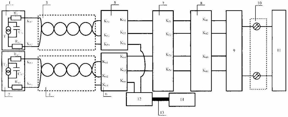
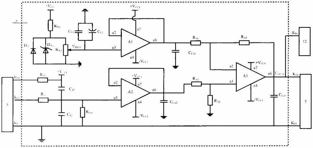
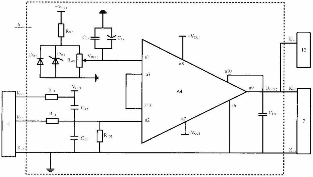
[0034] Such as figure 1 As shown, the temperature measuring device provided by the present invention includes first and second temperature sensor circuits 1 and 2, first and second double-core shielded twisted-pair wires 3 and 4, first and second adding and amplifying circuits 5 and 6, Data acquisition circuit 12 , computer 14 , comparison circuit 7 , photoelectric isolation conversion circuit 8 , electro-optic conversion circuit 9 , optical fiber 10 and remote over-temperature operating device 11 .

[0035] The first and second temperature sensor circuits 1 and 2 both use current output type integrated temperature sensors. During the test, the first and second temperature sensor circuits 1 and 2 installed on the object to be tested obtain current signals reflecting the temperature of the object to be tested, and transmit them to the The first and second ...


PUM


Abstract

The invention belongs to the temperature measuring technology, and is a long-distance temperature measuring device. The structure is: two current output type integrated temperature sensor circuits are connected to the input terminals of the addition amplifier circuit respectively through the double-core shielded twisted pair, and the output terminals of the addition amplifier circuit are divided into two channels and output to the data acquisition circuit and the comparison circuit. The circuit is connected to the computer via the USB interface, the data acquisition circuit collects and stores temperature data information in real time, and the computer analyzes the data obtained by the data acquisition circuit offline, which is convenient for drawing temperature curves and data analysis; the input end of the comparison circuit and the photoelectric isolation conversion circuit The output terminal of the photoelectric isolation conversion circuit is connected with the input terminal of the electro-optical conversion circuit, and the optical pulse signal obtained by the electro-optical conversion circuit is transmitted to the remote over-temperature operation device. Two sensors form two independent test channels, redundant work.

Description

technical field [0001] The invention belongs to a device for measuring temperature, and in particular relates to a long-distance temperature measuring device, which is suitable for relatively long-distance real-time monitoring, including a power electronic switch and its combination with a radiator (board), a circuit (board), a controller ( Box), monitoring platform (device) and other different measured body temperature. Background technique [0002] At present, for measuring the temperature of different measured objects such as power electronic switches and their combinations with radiators (boards), circuits (boards), controllers (boxes), and monitoring consoles (device), the more common sensors mainly include thermal resistors. , thermocouples, semiconductors and integrated temperature sensors, etc. Although the thermal resistance is low in cost, its reliability is not high and its accuracy is low. Although the price of the thermocouple is low, it needs cold junction com...

Claims


Application Information

Patent Timeline
Patent Type & Authority Patents(China)
IPC IPC(8): G01K7/00
Inventor 李维波贺洪宋晓龙马名中许金张明元饶金
Owner NAVAL UNIV OF ENG PLA
Learn More