Toner cartridge gear and transmission structure thereof

A technology of gear transmission and toner cartridge, applied in the field of toner cartridge gear and its transmission structure, can solve the problems of disengagement of the twisting head, high output cost, high precision of processing and assembly, and achieve smooth installation and removal, practicality Strong, low-cost effects

Inactive Publication Date: 2020-11-06
珠海泛能技术开发有限公司
View PDF7 Cites 0 Cited by
  • Summary
  • Abstract
  • Description
  • Claims
  • Application Information

AI Technical Summary

Problems solved by technology

At present, the structure of this kind of transmission parts is various. The toner cartridge gear of some manufacturers adopts the universal joint structure, which is easy to cause the twisted head to break away; the toner cartridge gear of some manufacturers adopts the auxiliary swing rod structure (such as CN201811493816. 7. CN201810941483.3, CN201610546864.2, CN201721239094.3 and other patented technical solutions), the meshing and separation of the toner cartridge gears of these auxiliary swing lever structures depends on the specific structure of the toner cartridge and its cooperation to realize its function smoothly, not Compatibility; the toner cartridge gears of some manufacturers (such as CN201610370265.0, CN201810515023.4, CN201821960347.0 and other patented technical solutions), these toner cartridge gears have a complex structure and process, and require high precision in processing and assembly. The output cost is high and it is not economically practical

Method used


Image

  • Toner cartridge gear and transmission structure thereof
  • Toner cartridge gear and transmission structure thereof
  • Toner cartridge gear and transmission structure thereof

Examples


Embodiment 1

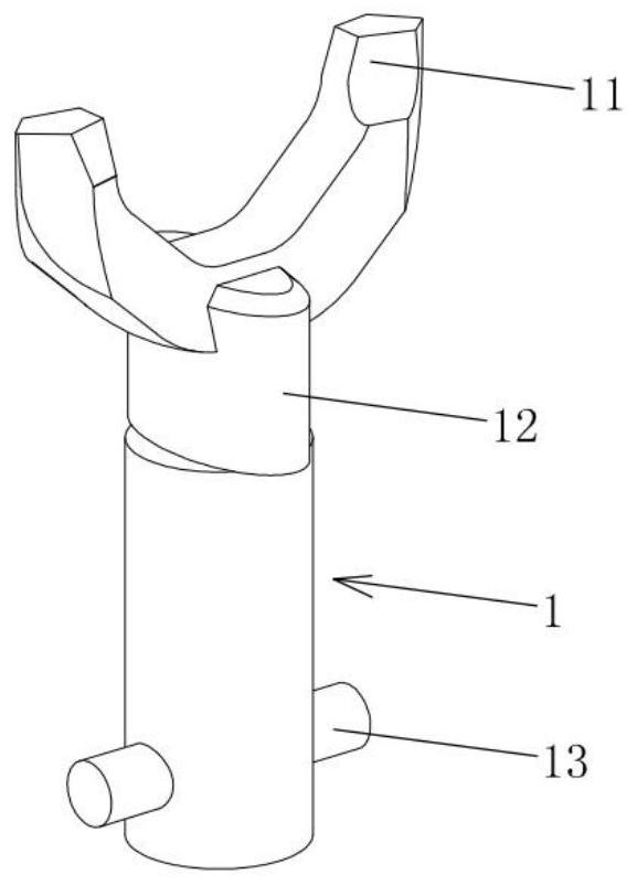
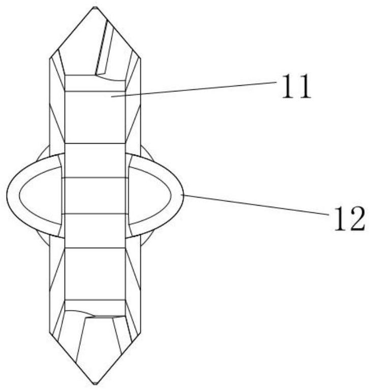
[0030] Embodiment 1: The coupling arm and the transmission part are assembled. The gear 2 is provided with a central shaft hole 20 for the transmission member 1 to extend out of the gear 2 . When installing, firstly, the lower part of the transmission part 1 passes through the central shaft hole 20 on the gear 2 and extends from the top of the groove cavity 21, and the lower part of the transmission part 1 passes through the groove cavity 21 and can protrude from the opening 22 at the bottom of the groove cavity 21. Cavity 21 outside. The coupler arm 13 is designed to slide axially into the rod-like structure inside the slot cavity 21 through the opening 23 at the bottom of the slot cavity 21 , and a plurality of openings 23 for the pair of coupler arms 13 to pass through are arranged along the outer circumference of the opening 22 . The inner end of the coupler arm 13 can be snap-connected with the clamping hole at the lower part of the transmission member 1 and then axially...


PUM


Abstract

The invention discloses and provides a toner cartridge gear and a transmission structure thereof. The transmission structure of the toner cartridge gear comprises a transmission part, gears and a spring, the transmission part is sequentially provided with a pair of meshing claws used for being meshed with a printer driving head, a non-cylindrical guide section used for adjusting the directions ofthe meshing claws, and a pair of coupling force arms used for driving a gear. A groove cavity adapting to 360-degree rotation of the coupling arm is formed in the gear; the top of the groove cavity isprovided with a pair of triangular transmission bosses used for being meshed with the couple arm, a spring enabling the couple arm to always keep moving towards the top of the groove cavity in the axial direction is arranged between the transmission part and the gear, and the toner cartridge gear obtains rotation driving motive power of the printer through transmission of the transmission part. The carbon powder box gear and the transmission part are simple in structure, low in cost, high in practicability, smooth in assembling and disassembling and capable of stably and reliably achieving power transmission.

Description

technical field [0001] The invention belongs to the technical field of toner cartridges, and in particular relates to a toner cartridge gear meshed with a driving head of a laser printer (including an all-in-one machine, a copier, and a facsimile machine) and a transmission structure thereof. Background technique [0002] Laser printers (including all-in-one machines, copiers, and fax machines) are equipped with a toner cartridge that can be loaded and taken out. The working motive force of the toner cartridge comes from the connection between the toner cartridge gear and the drive head of the printer. This requires that the transmission part of the toner cartridge gear and the drive head of the printer can be smoothly engaged and separated, and can run smoothly. At present, the structure of this kind of transmission parts is various. The toner cartridge gear of some manufacturers adopts the universal joint structure, which is easy to cause the twisted head to break away; th...

Claims


Application Information

Patent Timeline
Patent Type & Authority Applications(China)
IPC IPC(8): G03G15/08G03G21/16
CPCG03G15/0806G03G21/1647G03G21/1676
Inventor 刘晓敏
Owner 珠海泛能技术开发有限公司
Why Eureka
Try Eureka