Discharging device of shaft furnace
A technology of a shaft furnace and a driving device is applied in the field of discharge devices, which can solve the problems of shortening production time and the inability to discharge horizontally in a shaft furnace, and achieves the effects of shortening production time, facilitating equipment maintenance, and having a simple structure of the discharging device.
- Summary
- Abstract
- Description
- Claims
- Application Information
AI Technical Summary
Problems solved by technology
Method used
Image
Examples
Embodiment 1
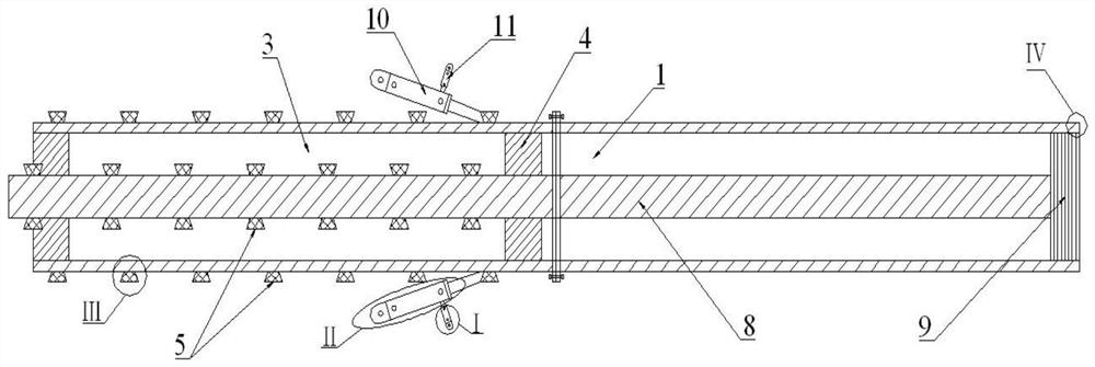
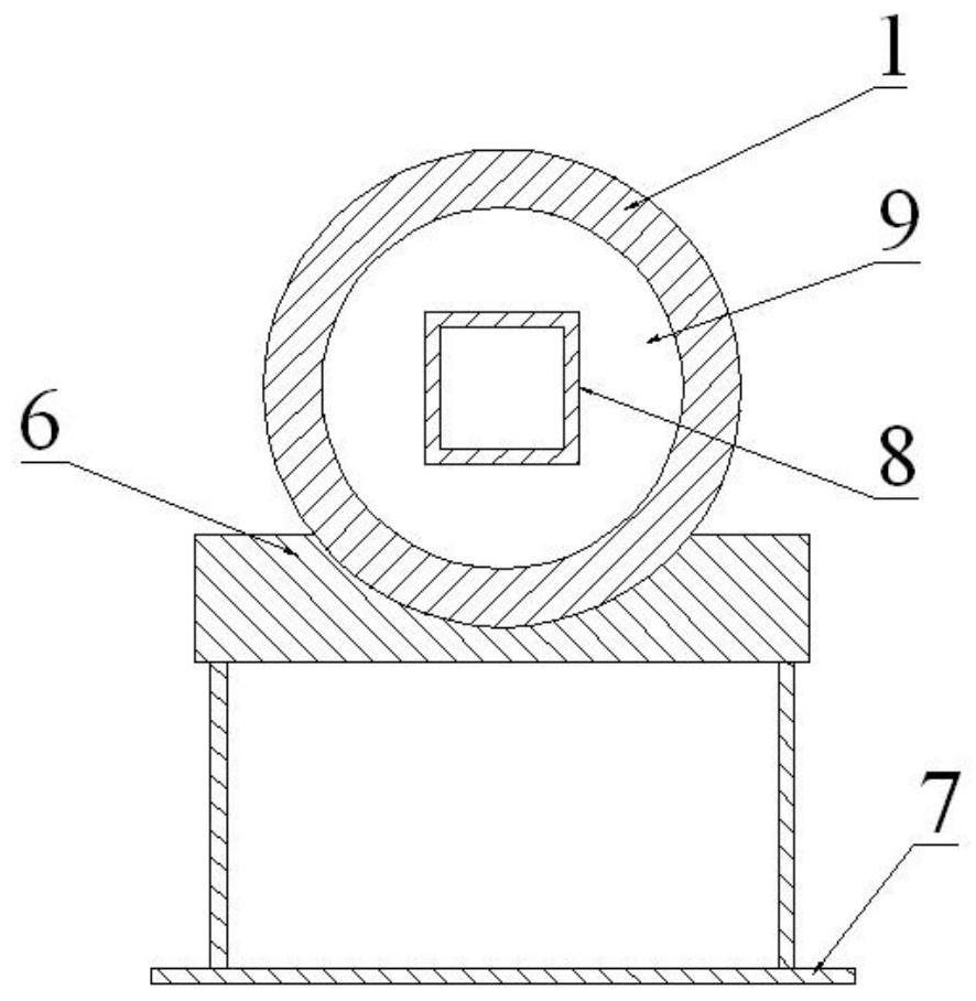
[0034] The supporting part adopts a hollow sleeve structure, and the discharge part is composed of a push plate and a push rod. The front end of the hollow sleeve is provided with convex teeth, and the tail end of the hollow sleeve is connected with the driving device; the inner cavity of the hollow sleeve slides with the push plate Cooperating, the pushing plate is flexibly connected with one end of the push rod, and the other end of the push rod is connected with the driving device.
[0035] The length of the hollow sleeve is not less than the distance between the two outlets of the reaction chamber, and the dimension of the longitudinal section of the hollow sleeve along the length direction is smaller than the size of the outlets. The hollow sleeve can adopt any cylindrical structure such as cylinder, square cylinder, inverted U-shaped cylinder, triangular cylinder and diamond-shaped cylinder, which can enter through the material layer from the discharge port at one end to ...
Embodiment 2
[0041] see Figure 9 to Figure 13 , when the support member adopts the support plate 14 structure, the shaft furnace reinforced furnace wall is provided with a horizontal boss along the direction of the discharge channel, and the boss is lower than the upper edge of the discharge port. The discharge member is composed of a second pusher plate 16 and a second push rod 17 and the like. The front end of the support plate 15 is provided with an inclined surface 18, the rear end of the support plate 14 is fixedly connected with the front end of the push plate 19, the upper plane of the push plate 19 is equipped with a double-sided rack 20, and the double-sided rack 20 is used to cooperate with the hydraulic motor 21. The lower part of the support plate 14 and the push plate 19 is slidably connected with the second positioning slideway 22, and the second positioning slideway 22 is fixed on the second frame body 24 through the first supporting device 23; the push plate 19 passes thro...
PUM
 Abstract
Description
Claims
Application Information
 - R&D Engineer
- R&D Manager
- IP Professional
- Industry Leading Data Capabilities
- Powerful AI technology
- Patent DNA Extraction
Browse by: Latest US Patents, China's latest patents, Technical Efficacy Thesaurus, Application Domain, Technology Topic, Popular Technical Reports.
© 2024 PatSnap. All rights reserved.Legal|Privacy policy|Modern Slavery Act Transparency Statement|Sitemap|About US| Contact US: help@patsnap.com


