
Noise reducing extractor hood

A range hood and noise reduction technology, which is applied in the field of kitchen appliances, can solve the problems of inability to absorb and reduce noise in medium and high frequency sound waves, loss of noise reduction function, etc. Effect

Pending Publication Date: 2020-11-06
GUANGDONG MACRO GAS APPLIANCE +1
View PDF2 Cites 0 Cited by
  • Summary
  • Abstract
  • Description
  • Claims
  • Application Information

AI Technical Summary

Problems solved by technology

For example, the Chinese patent application with application number 201310627547.X discloses a silent hood with a sound-absorbing cover, which includes a microporous cavity and filled with sound-absorbing cotton in the cavity. The principle of noise absorbs intermediate frequencies. Sound-absorbing cotton is a porous sound-absorbing material for resistive noise reduction. It mainly absorbs medium and high-frequency sound waves. However, the vent holes of porous sound-absorbing materials will be blocked after a period of time in the oil fume environment and form closed cells, losing noise reduction. function; another example is the Chinese patent application with application number 201810205739.4, which discloses a noise-reducing range hood, including a noise-reducing orifice plate, a front cover plate and an air flotation plate, which form a resonance noise-reduction cavity, and the resonance cavity noise reduction is a resistance elimination It is a form of the sound principle, which has obvious noise reduction performance for medium and low frequencies, but the noise reduction of the resonant cavity and the resonance frequency are related to physical quantities such as the volume of the resonant cavity. Frequency sound wave for absorption and noise reduction

Method used


Image

  • Noise reducing extractor hood
  • Noise reducing extractor hood
  • Noise reducing extractor hood

Examples


Embodiment Construction

[0029] This part will describe the specific embodiment of the present invention in detail, and the preferred embodiment of the present invention is shown in the accompanying drawings. Each technical feature and overall technical solution of the invention, but it should not be understood as a limitation on the protection scope of the present invention.

[0030] In the description of the present invention, it should be understood that the orientation descriptions, such as up, down, front, back, left, right, etc. indicated orientations or positional relationships are based on the orientations or positional relationships shown in the drawings, and are only In order to facilitate the description of the present invention and simplify the description, it does not indicate or imply that the device or element referred to must have a specific orientation, be constructed and operated in a specific orientation, and thus should not be construed as limiting the present invention.

[0031] I...


PUM


Abstract

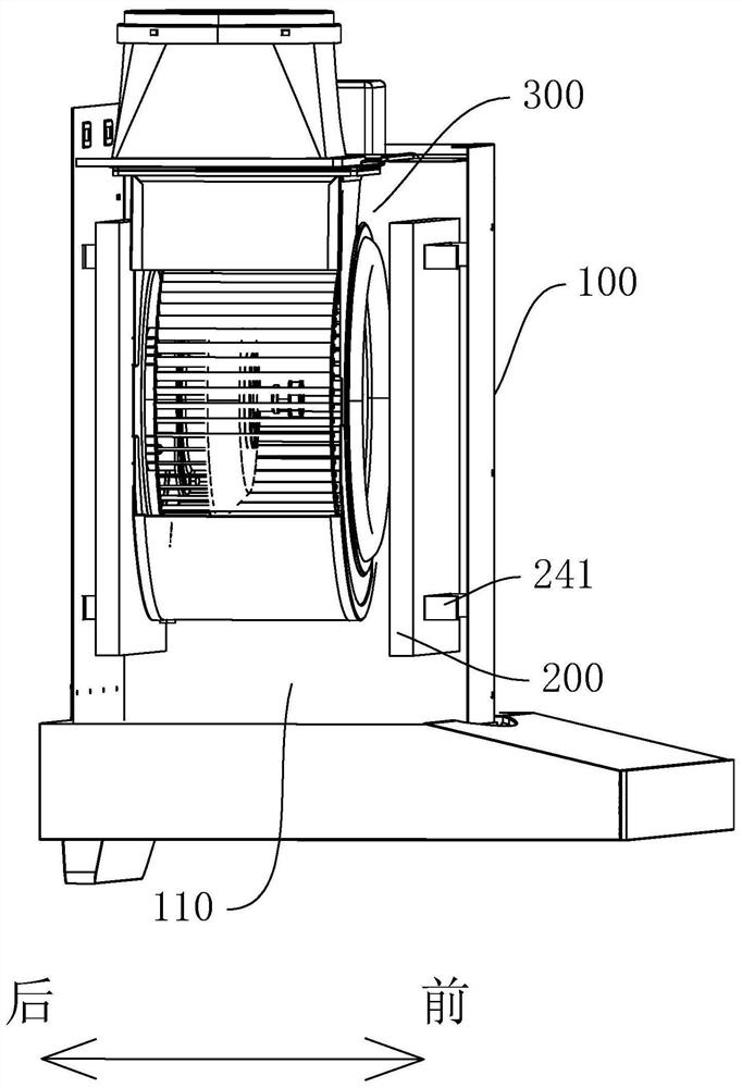
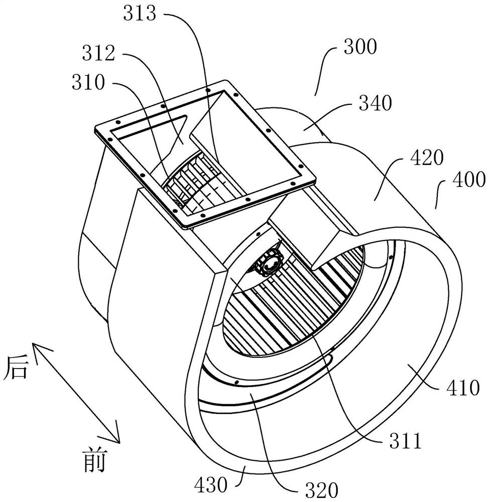
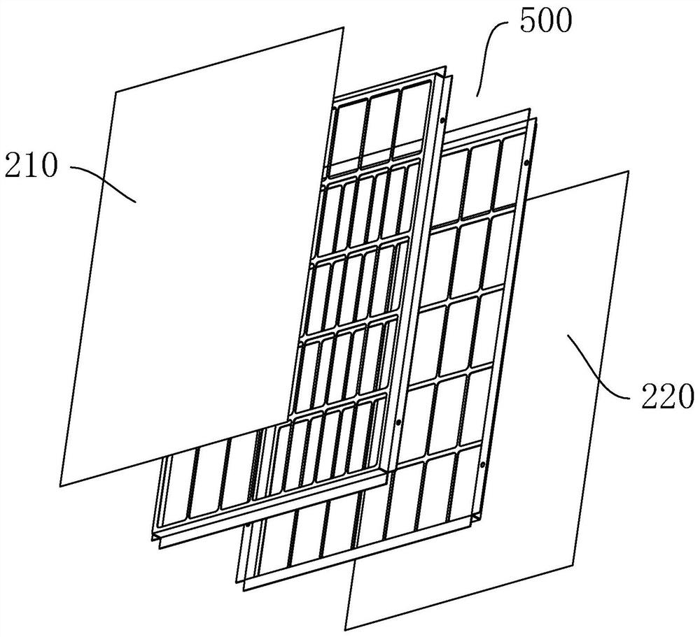
The invention discloses a noise reducing extractor hood. The extractor hood comprises a crate; the crate is provided with a fume collecting cavity; a draught fan device is installed inside the fume collecting cavity; a first noise reducing structure is arranged between the crate and the draught fan device; the first noise reducing structure comprises a first thin fill close to the draught fan device and a second thin film close to the inner wall of the fume collecting cavity; and a sealed first noise reducing cavity is formed between the first thin film and the second thin film. In the operation process of the extractor hood, a noise sound wave generated by operation of the draught fan device enters the first noise reducing cavity through the first thin film, and exits through the second thin film; under resonance action of the first thin film and the second thin film as well as the first noise reducing cavity, a sound absorption bandwidth is expanded and can absorb sound waves of different frequencies so the sound waves of different frequencies can be absorbed and reduced effectively; and the sealed first noise reducing cavity can effectively prevent fume from entering, working environment of the extractor hood is satisfied, and a good noise reducing function is maintained.

Description

technical field [0001] The invention relates to the field of kitchen appliances, in particular to a noise-reducing range hood. Background technique [0002] Range hoods have become the main kitchen appliances in modern families. With people's pursuit of a healthy life, people pay more and more attention to the noise of range hoods in addition to the effect of absorbing and exhausting range hoods during use. For example, the Chinese patent application with application number 201310627547.X discloses a silent hood with a sound-absorbing cover, which includes a microporous cavity and filled with sound-absorbing cotton in the cavity. The principle of noise absorbs intermediate frequencies. Sound-absorbing cotton is a porous sound-absorbing material for resistive noise reduction. It mainly absorbs medium and high-frequency sound waves. However, the vent holes of porous sound-absorbing materials will be blocked after a period of time in the oil fume environment and form closed cel...

Claims


Application Information

Patent Timeline
Patent Type & Authority Applications(China)
IPC IPC(8): F24C15/20
CPCF24C15/20
Inventor 艾穗江温永良林国汉
Owner GUANGDONG MACRO GAS APPLIANCE
Learn More