Gas flow vector control device

A technology of vector control and gas flow, applied to gas fuel burners, combustion methods, combustion types, etc., can solve the problems of poor versatility and low adaptability, and achieve the effect of convenient operation

Active Publication Date: 2020-11-06
欧保(中国)环境工程股份有限公司
View PDF8 Cites 2 Cited by
  • Summary
  • Abstract
  • Description
  • Claims
  • Application Information

AI Technical Summary

Problems solved by technology

[0002] In gas burners, in order to change the flow and velocity of the combustion-supporting air (air), the common method is to set a common damper and various control valves on the combustion-supporting air channel, which has poor adaptability and poor versatility

Method used


Image

  • Gas flow vector control device
  • Gas flow vector control device
  • Gas flow vector control device

Examples


Embodiment Construction

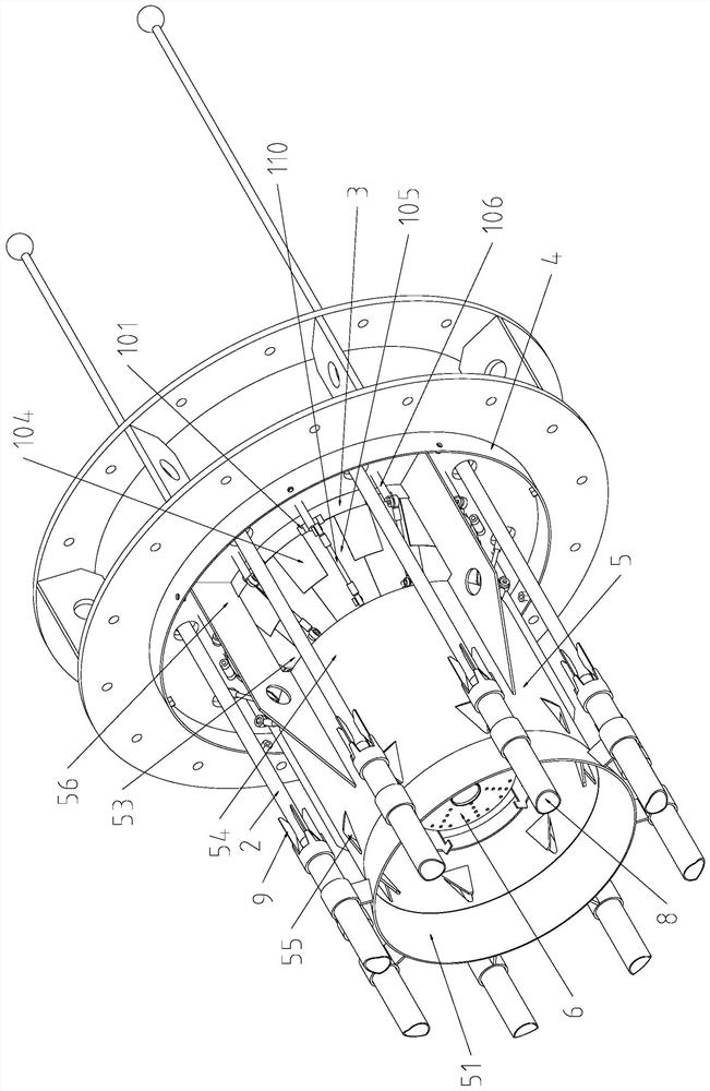
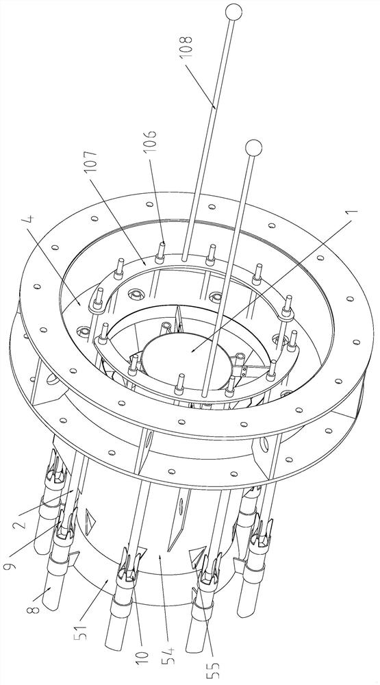
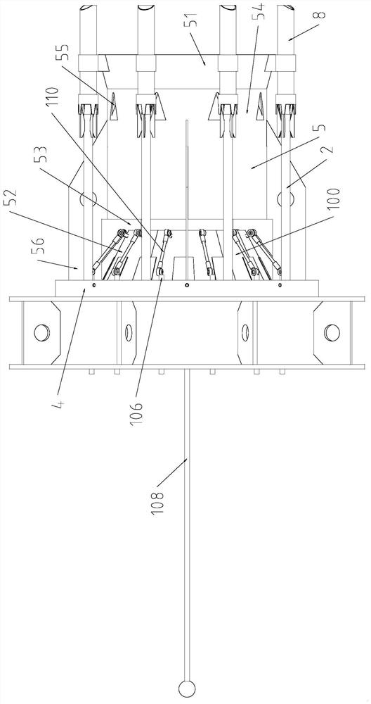
[0029] see figure 1 The vector control gas low-nitrogen burner using the gas flow vector control device shown includes a central air pipe 1, an outer ring air pipe 2, a housing 4 with an air channel (outlet channel) 3 inside, and the inlet of the air channel is connected to the fan (not shown) Draw) the exit is connected.

[0030] The air outlet pipe 5 includes a front section air outlet pipe 51, a middle section air outlet pipe 54 and a tapered rear section air outlet pipe 52 with a small front and a large rear, and the front section air outlet pipe 51 is a flared section with a large front and a small rear; The front end of the middle air outlet pipe 54 is docked with the flaring section, and the front end of the rear air outlet pipe 52 has a smaller diameter, forming a smoke gap 53 with the rear end of the middle air outlet pipe with a larger diameter. There are a plurality of smoke inlets 55 on the front side wall of the air outlet pipe 54 in the middle section; The air ...


PUM


Abstract

The invention provides a gas flow vector control device which is simple to operate, convenient to use and capable of changing the gas flow rate and the ventilation sectional area. The gas flow vectorcontrol device comprises a conical gas outlet valve which is connected to an outlet in the front end of a gas outlet channel and is small in front and large in rear, wherein the conical gas outlet valve comprises a plurality of diffusion blades arranged in the circumferential direction; the large end of each diffusion blade is connected with a port of the gas outlet channel in the radial directionof the conical gas outlet valve in a swinging mode; each diffusion blade is connected with a driving mechanism driving the diffusion blade to swing; a baffle is fixed to the inner side or / and the outer side of one of every two diffusion blades adjacent in the circumferential direction; and each baffle extends towards the other diffusion blade in the circumferential direction. When the driving mechanisms drive the diffusion blades to swing in the direction close to the axis of the conical gas outlet valve, the diameter of the small end of a conical gas outlet is reduced; and when the driving mechanisms drive the diffusion blades to swing in the direction away from the axis of the conical gas outlet valve and the diameter of the small end of the conical gas outlet is increased, gaps exist between the diffusion blades in the circumferential direction, and the baffles cover the gaps in the circumferential direction.

Description

technical field [0001] This patent relates to a gas flow control device for changing gas flow velocity and ventilation cross-sectional area, especially a combustion-supporting air flow control device for gas burners to change the combustion-supporting air flow velocity and ventilation cross-sectional area. Background technique [0002] In gas burners, in order to change the flow rate and velocity of the combustion-supporting air (air), the common method is to install ordinary dampers and various control valves on the combustion-supporting air channel, which has poor adaptability and poor versatility. Contents of the invention [0003] The purpose of this patent is to provide a gas flow vector control device which is simple to operate, easy to use, and capable of changing gas flow velocity and ventilation cross-sectional area. [0004] In order to achieve the stated purpose, the gas flow vector control device includes a small conical outlet valve connected to the outlet at ...

Claims


Application Information

Patent Timeline
Patent Type & Authority Applications(China)
IPC IPC(8): F23D14/60
CPCF23D14/60
Inventor 周国平
Owner 欧保(中国)环境工程股份有限公司
Why Eureka
Try Eureka