
Automatic precision pressure regulating valve

A precision pressure regulating valve and pressure regulating valve technology, applied in valve details, valve devices, engine components, etc., can solve the problems of slow adjustment speed, wrong value touch, and difficult value control, etc., to achieve adjustment speed block, data control, etc. handy effect

Inactive Publication Date: 2020-11-06
方博科技(深圳)有限公司
View PDF7 Cites 0 Cited by
  • Summary
  • Abstract
  • Description
  • Claims
  • Application Information

AI Technical Summary

Problems solved by technology

[0004] Based on the technical problem that the existing pressure regulating valve relies on manual adjustment, the adjustment speed is slow and the value is not easy to control, and at the same time, the value is easily affected by external factors such as accidental touches by workers and cannot be coordinated with the system. The present invention proposes automatic precision pressure regulation valve

Method used

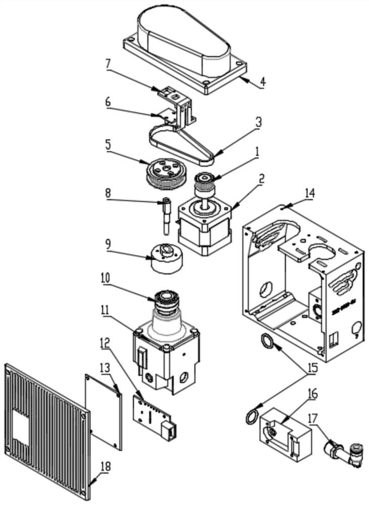
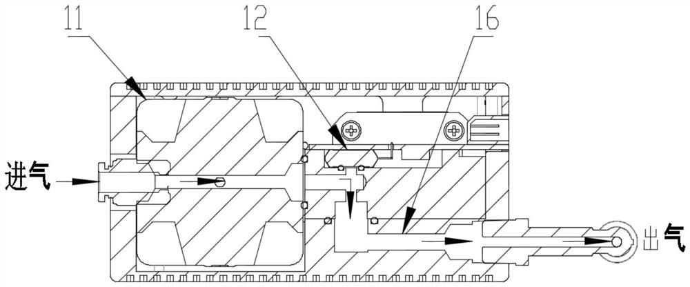
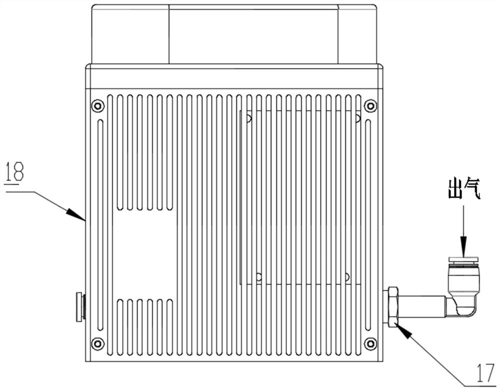

Image

  • Automatic precision pressure regulating valve
  • Automatic precision pressure regulating valve
  • Automatic precision pressure regulating valve

Examples


Embodiment

[0024] refer to Figure 1-3 , an automatic precision pressure regulating valve, including a base 14, a stepper motor 2 is fixed on one side of the inner wall of the base 14 by bolts, the top of the output shaft of the stepper motor 2 is fixed with a synchronous wheel a1 by screws, and the outer wall of the synchronous wheel a1 is sleeved with Synchronous belt 3, the inner wall of one side of the synchronous belt 3 is sleeved with a synchronous wheel b5, the inner wall of the synchronous wheel b5 is connected with an adjusting screw 8 through threads, and the inner wall of the bottom of the base 14 is fixed with a pressure regulating valve 11 by bolts, the pressure regulating valve 11 A bearing 10 is sleeved on the top end, and a pressure detection mechanism is provided on one side of the bottom outer wall of the base 14 .

[0025] In the present invention, the top outer wall of the pressure regulating valve 11 is fixed with a fixing seat 9 by screws.

[0026] In the present i...


PUM


Abstract

The invention discloses an automatic precision pressure regulating valve. The automatic precision pressure regulating valve is aimed at solving the problems that an existing pressure regulating valverelies on manual adjustment, and has low regulating speed, the numerical value of the existing pressure regulating valve is not easy to control, and is easily affected by external factors such as accidentally touching by workers, and the valve cannot be in joint debugging with a system. The following technical scheme is now put forward. The automatic precision pressure regulating valve comprises abase, wherein a stepping motor is fixed to the inner wall of one side of the base through a bolt; a synchronous wheel a is fixed to the top end of an output shaft of the stepping motor through a screw; the outer wall of the synchronous wheel a is in sleeve connection with a synchronous belt; the inner wall of one side of the synchronous belt is in sleeve connection with a synchronous wheel b; theinner wall of the synchronous wheel b is connected to an adjusting screw rod through a thread; a pressure regulating valve is fixed to the inner wall of the bottom of the base through a bolt; and thetop end of the pressure regulating valve is in sleeve connection with a bearing. Instructions are sent to the stepping motor in real time through a control board according to the feedback numerical value of a pressure acquisition board; the stepping motor drives the adjusting screw rod; a microswitch is touched through the adjusting screw rod so as to control the stepping motor without manual labor; and the joint debugging of the automatic precision pressure regulating valve and the system is realized.

Description

technical field [0001] The invention relates to the technical field of limit devices, in particular to an automatic precision pressure regulating valve. Background technique [0002] Pressure regulating valve, also known as self-operated balancing valve, flow control valve, flow controller, dynamic balancing valve, and flow balancing valve, is an intuitive and simple flow regulating control device. Pressure regulating valve, by driving the valve to change the cross-sectional area between the valve core and the valve seat, controls the flow, temperature, pressure and other process parameters of the pipeline medium to realize the regulating function. [0003] The adjustment of manual pressure regulating valves on the market requires manual adjustment. The adjustment speed is slow and the value is not easy to control. At the same time, the value is easily affected by external factors such as accidental touches by workers, and cannot be coordinated with the system. However, exis...

Claims


Application Information

Patent Timeline
Patent Type & Authority Applications(China)
IPC IPC(8): F16K31/04F16K37/00
CPCF16K31/046F16K31/047F16K37/005
Inventor 钟展锋刘清海
Owner 方博科技(深圳)有限公司
Learn More