
Rotary table

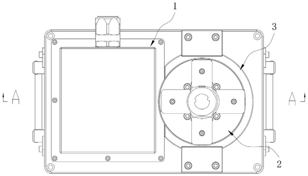
A technology of rotary table and rotary shaft, which is applied in the field of rotary table, can solve the problems of production accidents, workpiece flying out, poor grinding efficiency, etc., and achieve the effects of improving processing efficiency, avoiding safety accidents, and compact structure

Pending Publication Date: 2020-11-06
KEYIZHAN INTELLIGENT EQUIP CO LTD +1
View PDF0 Cites 0 Cited by
  • Summary
  • Abstract
  • Description
  • Claims
  • Application Information

AI Technical Summary

Problems solved by technology

[0002] When the equipment is assembled and used, there are usually certain requirements for the surface roughness of the parts. Since the surface of the workpiece is relatively rough after the mold is opened, in order to make the workpiece meet the required surface roughness, it is necessary to process the surface of the workpiece through the machining center. Grinding. In the prior art, the grinding tool such as the grinding rod is generally driven by the rotary device to rotate, and the surface of the workpiece is ground by the grinding side to achieve the effect of smoothing the surface of the workpiece. However, in the prior art, the grinding tool is usually rotated alone, and the workpiece Keep still, resulting in poor grinding efficiency;
[0003] In addition, the chucks for clamping workpieces in the prior art generally adopt pneumatic clamping. In the case of failure of the pneumatic equipment, the chuck loses the power to clamp the workpiece, and the workpiece is likely to fly out during processing, resulting in production accidents.

Method used


Image

  • Rotary table
  • Rotary table
  • Rotary table

Examples


Embodiment Construction

[0040] The specific implementation manners of the present invention will be further described in detail below in conjunction with the accompanying drawings and embodiments. The following examples are used to illustrate the present invention, but are not intended to limit the scope of the present invention.

[0041] In the description of the present invention, it should be noted that the orientation or positional relationship indicated by the terms "upper", "lower", "inner", "outer" and the like are based on the orientation or positional relationship shown in the accompanying drawings, and are only for It is convenient to describe the present invention and simplify the description, but does not indicate or imply that the device or element referred to must have a specific orientation, be constructed and operate in a specific orientation, and thus should not be construed as limiting the present invention.

[0042] In addition, terms "first", "second", etc. are used in the present...


PUM


Abstract

The invention relates to the technical field of machining centers, in particular to a rotary table. The rotary table comprises a rotary driving device, a clamp, and an annular air cylinder. The rotarydriving device comprises a rotating shaft. The clamp comprises a chuck, an elastic piece and at least two sets of clamping pieces, the clamping pieces are arranged on the chuck and can move in the radial direction of the chuck, and the elastic piece abuts against the clamping pieces. The annular air cylinder comprises an annular piston, and the rotating shaft penetrates through the inner side ofthe annular piston in the radial direction. The output end of the rotating shaft is fixedly connected with the chuck, the elastic piece pushes the at least two sets of clamping pieces to move inwardsin the radial direction of the chuck so as to lock a workpiece, and the annular piston moves in the axial direction so that the clamping pieces can be pushed to move outwards in the radial direction of the chuck so as to unlock the workpiece. Firstly, the machining efficiency of a product capable of being rotationally machined is greatly improved; secondly, the reliability and stability of the clamp clamping the workpiece are improved, and the production cost is reduced; and thirdly, the structure of the rotary table is more compact.

Description

technical field [0001] The invention relates to the technical field of machining centers, in particular to a rotary table. Background technique [0002] When the equipment is assembled and used, there are usually certain requirements for the surface roughness of the parts. Since the surface of the workpiece is relatively rough after the mold is opened, in order to make the workpiece meet the required surface roughness, it is necessary to process the surface of the workpiece through the machining center. Grinding. In the prior art, the grinding tool such as the grinding rod is generally driven by the rotary device to rotate, and the surface of the workpiece is ground by the grinding side to achieve the effect of smoothing the surface of the workpiece. However, in the prior art, the grinding tool is usually rotated alone, and the workpiece Keep still, resulting in poor grinding efficiency; [0003] In addition, the chucks for clamping workpieces in the prior art generally use...

Claims


Application Information

Patent Timeline
Patent Type & Authority Applications(China)
IPC IPC(8): F15B15/08F15B15/20
CPCF15B15/08F15B15/20
Inventor 颜炳姜朱小康李俊宏
Owner KEYIZHAN INTELLIGENT EQUIP CO LTD
Learn More