An auxiliary reinforcement adding device for the manufacture of reinforced concrete columns
A reinforced concrete, action technology, applied in the direction of manufacturing tools, ceramic molding machines, etc., can solve the problems of cumbersome operation of steel bars, low work efficiency, manpower consumption, etc., and achieve the effect of saving manpower, improving work efficiency, and simple operation
- Summary
- Abstract
- Description
- Claims
- Application Information
AI Technical Summary
Problems solved by technology
Method used
Image


Examples
Embodiment 1
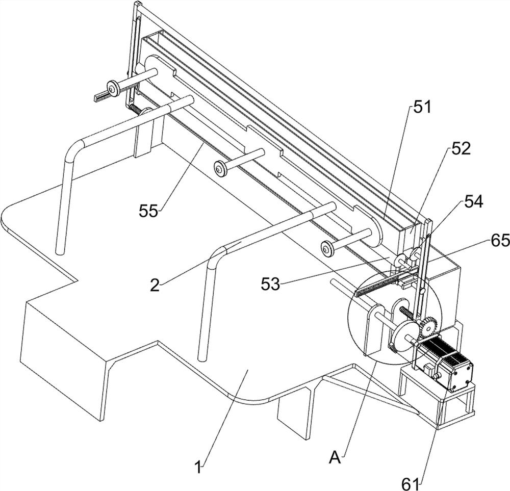
[0026] An auxiliary reinforcement device for reinforced concrete column fabrication, such as Figure 1-4 As shown, it includes a support seat 1, a fixed frame 2, a mold 3 and a fixed plate 4, the top of the support seat 1 is connected with the fixed frame 2, the right side of the top of the support seat 1 is connected with the mold 3, and the top of the support seat 1 on the left front of the mold 3 A fixed plate 4 is connected, and a blanking assembly 5 and a driving assembly 6 are also included. The blanking assembly 5 is provided on the fixed frame 2 , and the driving assembly 6 is provided on the support base 1 .
[0027] The blanking assembly 5 includes a material storage frame 51, a connecting plate 52, a docking cylinder 53, a grooved roller 54, a partition plate 55, a sliding frame 56, a compression spring 57 and a connecting shaft 58, and the fixed frame 2 is slidably connected with a material storage frame 51, the front side of the material storage frame 51 is connec...
Embodiment 2
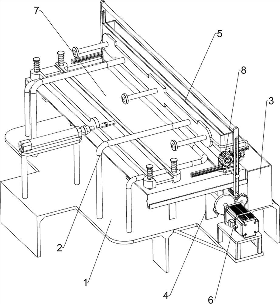
[0031] On the basis of Example 1, such as Figure 5-6As shown, a vibration assembly 7 is also included, and the vibration assembly 7 includes a guide rail 71, a slide plate 72, a cylinder 73, a vibration plate 74, an elastic member 75, a sector gear 76, a shaft rod 77, a driving gear 78, a rotating disk 79, and a slide block 791 And connecting rod 792, support base 1 top left side is connected with guide rail 71, slide type is connected with slide plate 72 on guide rail 71, and the support base 1 top on guide rail 71 left side is equipped with cylinder 73, and the telescoping link of cylinder 73 is connected with slide plate 72, A vibration plate 74 is slidably connected to the slide plate 72, an elastic member 75 is connected between the vibration plate 74 and the slide plate 72, a sector gear 76 is connected to the rear end of the first rotating shaft 62, and a shaft rod 77 is rotatably connected to the top right side of the support seat 1. The front part of the shaft rod 77...
Embodiment 3
[0034] On the basis of Example 2, such as Figure 5 As shown, a rotating assembly 8 is also included. The rotating assembly 8 includes a connecting frame 81, a driving rack 82, a first one-way gear 83 and a second one-way gear 84. The front side of the fixed frame 2 is connected to the connecting frame 81, and the A drive rack 82 is connected to the frame 81, a first one-way gear 83 is connected to the grooved roller 54 on the right side, a second one-way gear 84 is connected to the grooved roller 54 on the left side, and the first one-way gear 83 is connected to the first one-way gear 83. The two one-way gears 84 mesh, the second one-way gear 84 is longer than the first one-way gear 83 , and the driving rack 82 meshes with the second one-way gear 84 .
[0035] The material storage frame 51 drives the first one-way gear 83 and the second one-way gear 84 to move back and forth when it reciprocates left and right. When the second one-way gear 84 moves to the right to mesh with t...
PUM
 Abstract
Description
Claims
Application Information
 - R&D
- Intellectual Property
- Life Sciences
- Materials
- Tech Scout
- Unparalleled Data Quality
- Higher Quality Content
- 60% Fewer Hallucinations
Browse by: Latest US Patents, China's latest patents, Technical Efficacy Thesaurus, Application Domain, Technology Topic, Popular Technical Reports.
© 2025 PatSnap. All rights reserved.Legal|Privacy policy|Modern Slavery Act Transparency Statement|Sitemap|About US| Contact US: help@patsnap.com