


Quick Research
Generate reliable direction feasibility study reports for your R&D in just a few steps.

Technical Q&A
Discover and master advanced knowledge NOW. Basics, ideas, possibilities, all at once.

Find Solutions
As an expert in R&D theories, this can generate solutions to your technical problems instantly.

Evaluate Feasibility
Analyze your overall solution with one click, know your potential R&D risks in advance.

Monitor Landscape
Get weekly tech updates, stay abreast of the latest tech innovations and key insights.
A hot runner protection structure and guide pillars thereof
A hot runner plate and guide post technology, applied in the field of molds, can solve the problems affecting the guiding function of the guide post, the deformation of the end of the guide post, and the easy damage of the guide post, so as to improve the service life, avoid wear and deformation, and improve the guiding performance. Effect
- Summary
- Abstract
- Description
- Claims
- Application Information
AI Technical Summary
Problems solved by technology
Method used
Image

Examples
Embodiment 1
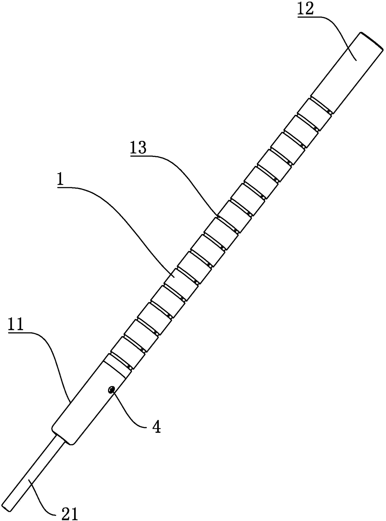
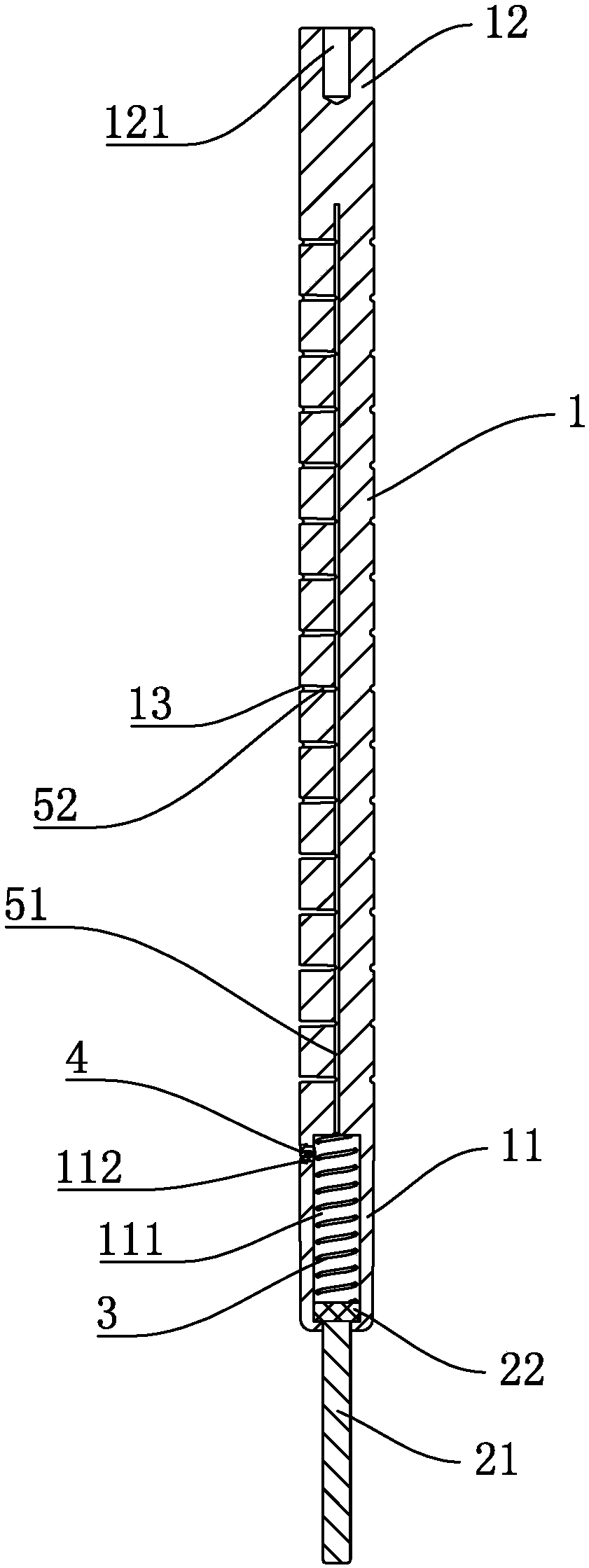
[0037] Embodiment 1, a kind of guide post, see attached figure 1 and 2 , the guide post includes a cylinder 1, one end of the cylinder 1 is provided with an installation end 12, and the end of the installation end 12 is provided with an installation threaded hole 121; the other end of the cylinder 1 is an insertion end 11, through which the end is inserted into the The guide post cooperates with the guide hole to realize the guiding function; the end of the guide part is provided with a supporting foot, and the supporting foot can be directly fixed and installed on the end of the insertion end 11, or the supporting foot can be divided into two parts as in the first embodiment. It is a sliding block 22 and a supporting foot, wherein the sliding block 22 cooperates and slides in the sliding cavity 111 of the insertion end 11, and a spring 3 for reset is provided between the sliding block and the bottom of the sliding cavity 111; For details, see the attached figure 2 , an oil...
Embodiment 2
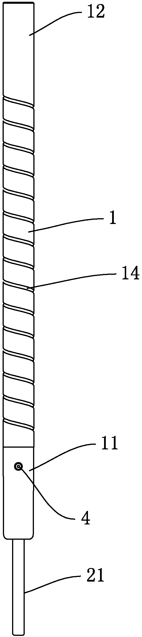
[0039] Embodiment two, a kind of guide post, see attached image 3 and 4 , the difference from Embodiment 1 is that the annular oil groove 13 originally arranged on the outer wall of the cylinder 1 is replaced by the spiral oil groove 14 surrounding the cylinder 1, and the first oil guide passage 51 and the spiral oil groove 14 pass through The third oil guide channel realizes Unicom. The third oil guide channel is arranged at intervals along the axial direction of the first oil guide channel 51, and the oil lubricating groove is arranged as a spiral oil groove 14 spirally rising along the column body 1, and the oil path lubricates The length is long, even if there are burrs and other phenomena in the oil groove, because it is not perpendicular to the guiding direction, but has a certain angle, the influence on the guiding accuracy is smaller than that of the horizontal annular oil groove 13.
Embodiment 3
[0040] Embodiment 3, a hot runner protection structure, see attached Figure 5 , what is used here is the guide post in the first embodiment, of course, the guide post in the second embodiment can also be selected, the hot runner protection structure includes a fixed mold seat plate 6, a hot runner plate 7, and a The hot runner, the hot nozzle 8 of the hot runner protrudes through the hot runner plate 7, and four guide posts in the first embodiment are arranged on the hot runner plate 7, and the length of the column 1 is longer than the length of the hot nozzle 8.
[0041] When installing the hot runner protection structure and the fixed mold, the guide post is installed in alignment with the guide hole on the fixed mold, which realizes the convenient installation effect of the hot runner protection structure and the fixed mold, and through the annular lubricating groove set on the column body 1, When inserting into the guide hole of the fixed mold, the problem of dry friction...
PUM
 Abstract
Description
Claims
Application Information
 - R&D Engineer
- R&D Manager
- IP Professional
- Industry Leading Data Capabilities
- Powerful AI technology
- Patent DNA Extraction
Browse by: Latest US Patents, China's latest patents, Technical Efficacy Thesaurus, Application Domain, Technology Topic, Popular Technical Reports.
© 2024 PatSnap. All rights reserved.Legal|Privacy policy|Modern Slavery Act Transparency Statement|Sitemap|About US| Contact US: help@patsnap.com