Intelligent multifunctional manipulator
A multi-functional manipulator and machine compartment technology, applied in the field of manipulators, can solve the problems of inconvenient transportation and storage, single function of the manipulator, and reduce the storage area of the manipulator, so as to increase the distance of handling or pick-and-place, facilitate transport and storage, and reduce The effect of storage area
- Summary
- Abstract
- Description
- Claims
- Application Information
AI Technical Summary
Problems solved by technology
Method used
Image
Examples
Embodiment 1
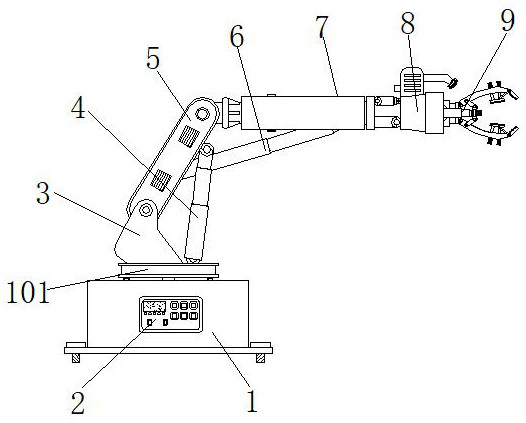
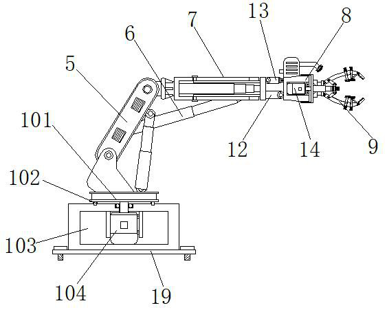
[0033] Example 1, such as Figure 1-2 As shown, when the entire manipulator needs to be folded, the support rod 5 can be propped up to a vertical state by the pneumatic cylinder A4, and then the installation pipe 701 can be folded and folded by shortening the air cylinder B6, so that the installation pipe 701 and the support rod 5 are close together Together, the intelligent manipulator can be folded freely when not in use.
Embodiment 2
[0034] Example 2, such as Figure 1-4 As shown, when the clamping part of the manipulator needs to be extended, the components on the mounting plate 706 can be extended to a farther distance through the pneumatic cylinder C702, and the limiting block 704 slides inside the limiting groove 703, while The movable pipe 705 slides out from the inside of the installation pipe 701, so that the gripping structure of the manipulator installed on the installation plate 706 can extend to a farther distance, and the air cylinder D13 can be extended or shortened, so that the machine compartment 8 can be connected with the position of the connecting plate 12. The hinge is where the rotating shaft rotates in the range of 0° to 90°.
Embodiment 3
[0035] Example 3, such as Figure 5-7 As shown, when an object needs to be clamped, the electric elevating rod 161 is extended to force the two sets of arc splints 9 to close together, thereby clamping the object. Resist and gradually move to the inner side of the arc-shaped splint 9. During the process, the spring 172 is stressed and stretched, and the two sets of baffles 175 gradually rotate to the inner side of the arc-shaped splint 9. The inner side of the arc-shaped splint 9 is driven by the servo motor B14 to rotate the components on the cover 10 at a slight angle, so that the clamped object can be adjusted to a suitable angle for placement.
[0036] Working principle: Connect the device to the power supply before use. When using the manipulator, the servo motor A104 drives the turntable 101 to rotate, so that the components such as the machine compartment 8 and the arc splint 9 face the direction of the object, and then shorten the air cylinder A4 to make the support T...
PUM
 Abstract
Description
Claims
Application Information
 - R&D Engineer
- R&D Manager
- IP Professional
- Industry Leading Data Capabilities
- Powerful AI technology
- Patent DNA Extraction
Browse by: Latest US Patents, China's latest patents, Technical Efficacy Thesaurus, Application Domain, Technology Topic, Popular Technical Reports.
© 2024 PatSnap. All rights reserved.Legal|Privacy policy|Modern Slavery Act Transparency Statement|Sitemap|About US| Contact US: help@patsnap.com


