
Micro power supply and energy storage real-time regulation and control method

A technology of real-time regulation and micro-power supply, which is applied in the direction of energy storage, electrical components, circuit devices, etc., can solve the problem of not considering the power supply priority and maximum charging and discharging power of the energy storage system, and the high capacity configuration requirements of the energy storage system, which cannot meet the requirements Special working conditions and other issues, to achieve the effect of improving the utilization rate of renewable energy, good economy, and maximizing economic benefits

Inactive Publication Date: 2020-11-03
NORTHEAST DIANLI UNIVERSITY
View PDF6 Cites 4 Cited by
  • Summary
  • Abstract
  • Description
  • Claims
  • Application Information

AI Technical Summary

Problems solved by technology

At present, the existing patents mainly focus on the optimization and regulation of the charge and discharge of the energy storage system. For example: Chinese patent application number 201710335556. The instruction of energy storage charging and discharging does not consider the constraints of power supply priority and maximum charging and discharging power of the energy storage system, so it cannot meet some special working conditions, and the applicability is poor. economy

Method used


Image

  • Micro power supply and energy storage real-time regulation and control method
  • Micro power supply and energy storage real-time regulation and control method
  • Micro power supply and energy storage real-time regulation and control method

Examples


Embodiment Construction

[0069] The present invention will be described in further detail below in conjunction with the accompanying drawings and embodiments.

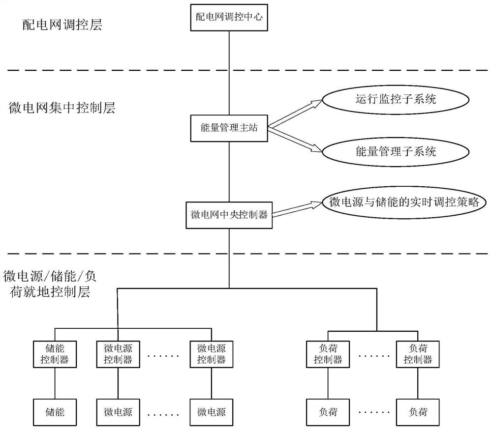
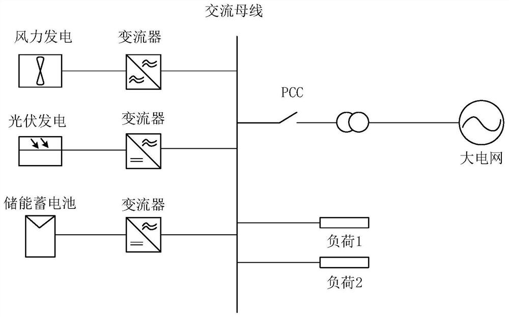
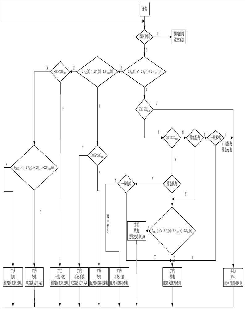
[0070] refer to figure 1 , a real-time control method of micro power supply and energy storage in the present invention, no longer only relies on the state of charge of the energy storage as the instruction for charging and discharging the energy storage system, but also considers constraints such as the priority of energy storage power supply and the maximum charging and discharging power, In the case of knowing the peak and valley load occurrence time of the system, the power supply priority of the energy storage system is divided into three levels, namely energy storage priority, mains power priority and general mode, and the load is divided into important load and controllable load. The operation of reducing the output of micro-sources through load shedding satisfies the operation of micro-grids under various working conditions, and gives ...


PUM


Abstract

A micro power supply and energy storage real-time regulation and control method is characterized in that the charging and discharging state of an energy storage system does not only depend on the energy storage SOC state any more, and constraint conditions such as the energy storage power supply priority and the maximum charging and discharging power are considered at the same time; during grid-connected operation, an energy storage power supply mode is divided into an energy storage priority mode, a mains supply priority mode and a general mode under the condition that the peak-valley flat load occurrence time of the system is known,the peak clipping and valley filling are achieved, the micro power supply output fluctuation is stabilized, the renewable energy utilization rate is increased, and economic benefits are maximized; during off-grid operation, loads are divided into important loads and controllable loads, micro-grid operation under various working conditions is met through load shedding, micro-source output reduction and other operations, and a specific load shedding value and a reduced micro-source output value are given; and the reduced micro-source output is distributed to each distributed micro-source for common bearing according to the weight by utilizing a weighted distribution method, so that the uninterruptible power of the important load is ensured, the energy utilization efficiency is maximized, and the operation of the microgrid is stable.

Description

technical field [0001] The invention relates to the technical field of micro-grid energy management systems, in particular to a method for real-time regulation of micro-power sources and energy storage. Background technique [0002] With the development of new energy power generation and micro-grid technology, more and more new energy power generation is connected to the micro-grid. However, the power generation power of renewable energy such as wind and rain is extremely sensitive to changes in the external weather, making its output power appear random. Especially with the gradual increase of its power generation ratio, if it is directly connected to the power system without effective control, it will cause bus voltage and frequency fluctuations. In severe cases, its voltage frequency may exceed the allowable range, causing local The network crashes. Therefore, the energy storage system is particularly important in the entire microgrid system. The energy storage system c...

Claims


Application Information

Patent Timeline
IPC IPC(8): H02J3/00H02J3/28H02J3/32H02J3/38H02J3/46H02J3/48
CPCH02J3/00H02J3/28H02J3/32H02J3/381H02J3/48H02J3/466Y02E70/30
Inventor 李波陈乐乐杨少布道李健
Owner NORTHEAST DIANLI UNIVERSITY
Learn More