Method for testing optical image stabilization performance of camera driving motor

A technology for driving motors and testing methods, which is applied in optical instrument testing, vibration testing, machine/structural component testing, etc. It can solve the problems of camera module sample scrapping, production cost increase, OIS performance evaluation, etc. The effect of reaching the standard, increasing production efficiency, and avoiding rework and maintenance

Active Publication Date: 2020-11-03
CHANGZHOU RAYTECH OPTRONICS CO LTD
View PDF7 Cites 2 Cited by
  • Summary
  • Abstract
  • Description
  • Claims
  • Application Information

AI Technical Summary

Problems solved by technology

This evaluation method needs to install the camera module and gyroscope on the signal conversion module and fix them together on the shaker table, and only after the camera module is fully assembled, it can be taken with normal power on and image analysis can be carried out smoothly. However, it is impossible to evaluate the OIS performance of the camera drive motor (motor unit) in the camera module at the stage of incoming materials. At this time, once the OIS performance of the camera drive motor does not meet the standard, the assembled camera module samples will be scrapped , which increases the risk that the production yield rate does not meet the standard; at the same time, reassembly after rework and debugging of OIS control parameters will also result in low production efficiency and increased production costs

Method used


Image

  • Method for testing optical image stabilization performance of camera driving motor
  • Method for testing optical image stabilization performance of camera driving motor
  • Method for testing optical image stabilization performance of camera driving motor

Examples


Embodiment Construction

[0031] The present invention will be further described below in conjunction with the accompanying drawings and embodiments.

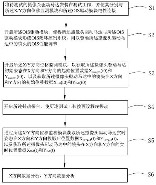
[0032] Please also see Figure 1-2 , the present invention provides a method for testing optical image stabilization performance of a camera drive motor, providing:

[0033] Shaking vibration table 1 is used to simulate the shaking process of actual hand-held shooting by people.

[0034] The test fixture 2 is used to mount the camera drive motor 10 carrying the lens 101 , which includes an X / Y direction displacement monitoring module 21 and an OIS drive module 22 .

[0035] In this embodiment, the camera drive motor 10 is built-in to detect the X-direction and Y-direction displacement of the internal lens 101 and generate the Hall signal X respectively. Hall There are at least two groups of Hall sensors, that is, a group of X-direction Hall sensors 102a for detecting the displacement of the lens 101 in the X direction and a group of Y-direction Hall s...


PUM


Abstract

The invention provides a method for testing the optical image stabilization performance of a camera driving motor, and the method comprises the following steps: enabling the camera driving motor to beinstalled on a testing tool, and enabling the camera driving motor to be electrically connected with an X-direction displacement monitoring module, a Y-direction displacement monitoring module and anOIS driving module; starting the OIS driving module so as to enable the camera driving motor and the OIS driving module to form an OIS closed-loop control system; starting an X-direction displacementmonitoring module and a Y-direction displacement monitoring module to obtain X-direction initial position data and Y-direction initial position data of a camera driving motor; starting a shaking table; obtaining real-time X-direction and Y-direction displacement data of a camera driving motor through an X-direction displacement monitoring module and a Y-direction displacement monitoring module; and enabling the upper computer to analyze the X-direction data and the Y-direction data to judge whether the OIS performance reaches the standard or not. Compared with the prior art, the method for testing the optical image stabilization performance of the camera driving motor is good in reliability, the production efficiency is effectively improved, and the production cost and the reject ratio risk are reduced.

Description

technical field [0001] The invention relates to a test method, in particular to a test method for optical image stabilization performance of a camera driving motor used in the field of portable camera electronic products. Background technique [0002] In recent years, micro-motor control systems with OIS (Optical Image Stabilization) functions have been adopted by many high-end mobile phone camera modules. In order to ensure that the camera module has excellent OIS performance, the camera module factory usually tests the actual imaging effect of the camera module sample on the shaking table before shipment, and uses the calculated SR (Suppression Ratio, suppression Ratio) parameters are used as the criterion for judging the performance of OIS. This evaluation method needs to install the camera module and gyroscope on the signal conversion module and fix them together on the shaker table, and only after the camera module is fully assembled, it can be taken with normal power ...

Claims


Application Information

Patent Timeline
Patent Type & Authority Applications(China)
IPC IPC(8): G01M11/00G01M7/02
CPCG01M11/00G01M7/022G01M7/025G01M7/027
Inventor 张超吴志江张启
Owner CHANGZHOU RAYTECH OPTRONICS CO LTD
Why Eureka
Try Eureka