Variable compression ratio engine

A technology of engine and compression ratio, which is applied in the direction of engine control, machine/engine, mechanical equipment, etc., and can solve the problem of slow adjustment of compression ratio

Active Publication Date: 2020-11-03
DONGFENG MOTOR CORP HUBEI
View PDF6 Cites 1 Cited by
  • Summary
  • Abstract
  • Description
  • Claims
  • Application Information

AI Technical Summary

Problems solved by technology

[0005] The embodiment of the present invention provides a variable compression ratio engine to solve the technical problem of slow adjustment speed of the existing engine compression ratio in the related art

Method used


Image

  • Variable compression ratio engine
  • Variable compression ratio engine
  • Variable compression ratio engine

Examples


Embodiment 1

[0030] The embodiment of the present invention provides a variable compression ratio engine, which can solve the technical problem of slow adjustment speed of the existing engine compression ratio.

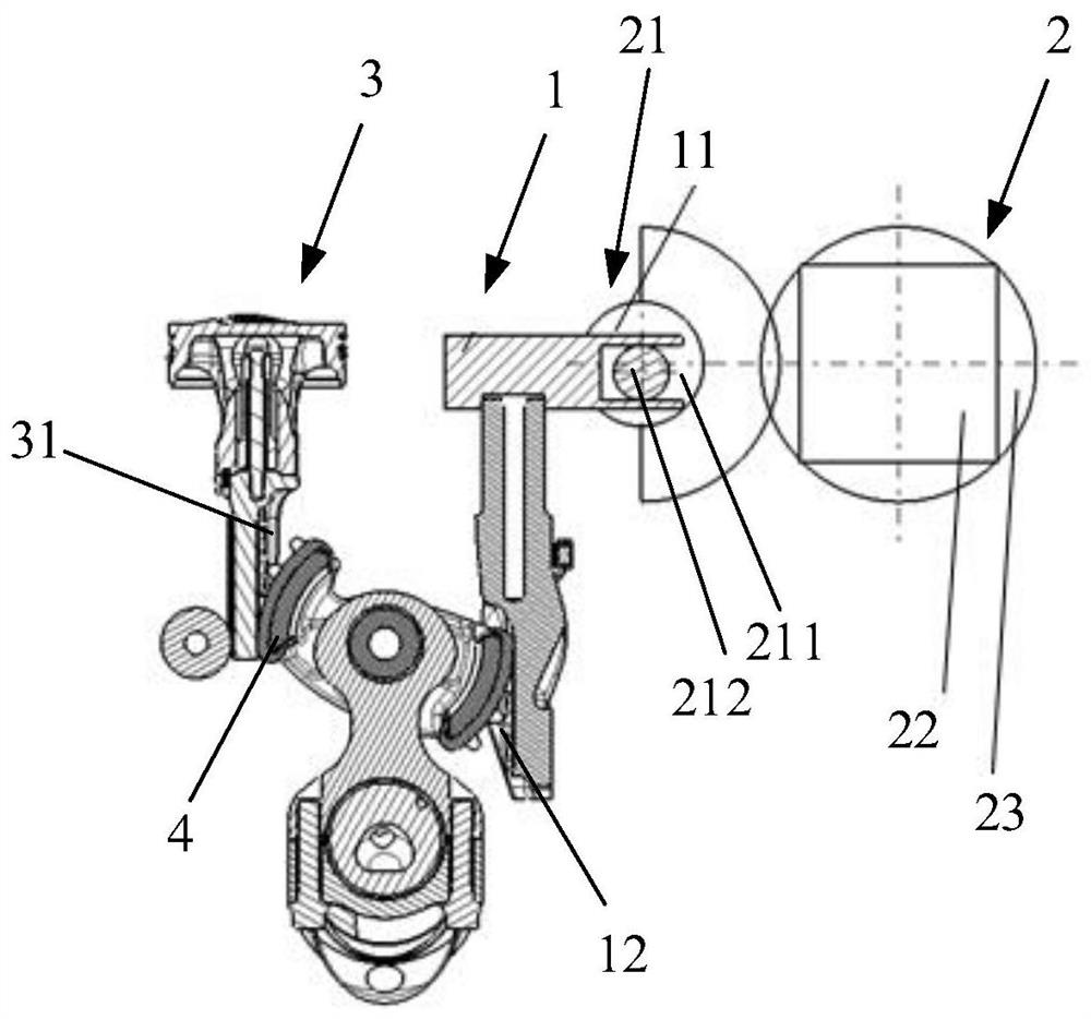
[0031] See figure 2 As shown, a variable compression ratio engine includes: a control piston 1 and a driving and locking mechanism 2.

[0032] The control piston 1 and the cylinder piston 3 of the engine are arranged side by side. The control piston 1 is configured to drive the cylinder piston 3 to move downward or upward when the control piston 1 moves up or down to adjust the top dead center position of the cylinder piston 3 , And the control piston 1 is provided with a clamping portion 11.

[0033] The driving and locking mechanism 2 is provided on the side of the control piston 1, and the driving and locking mechanism 2 is provided with a movable part 21 movably connected with the clamping part 11, and the movable part 21 is used to drive the control piston 1 to move up or down, or ...

Embodiment 2

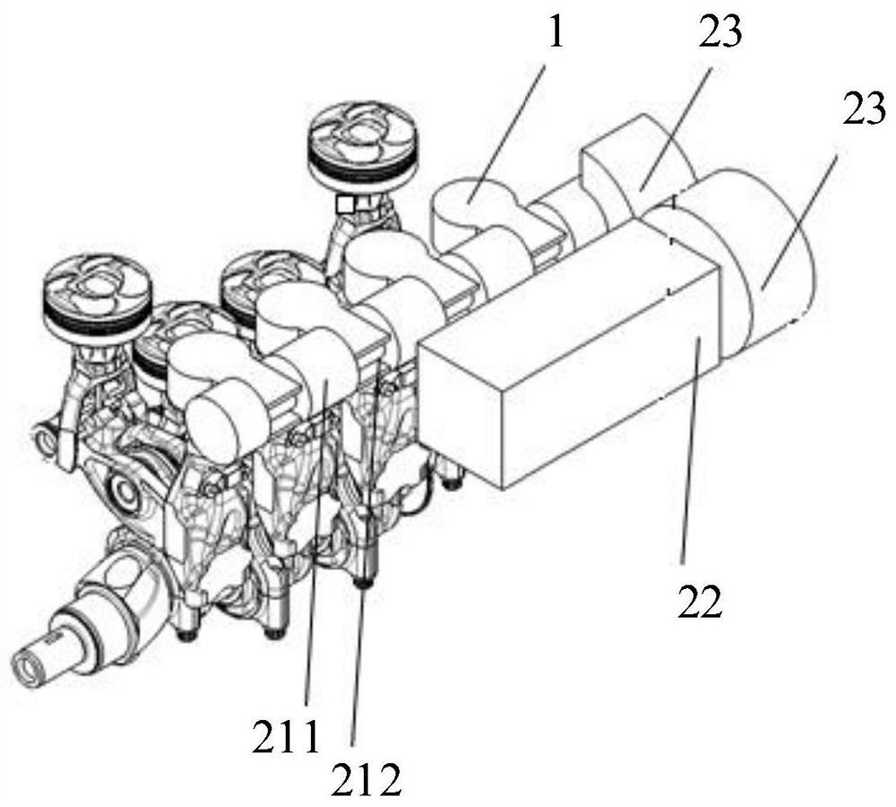
[0036] On the basis of Example 1, see figure 2 As shown, as an optional embodiment: the clamping portion 11 is a rectangular opening groove opened at the upper end of the control piston 1. The movable part 21 includes a rotating shaft 211 and an eccentric shaft 212 provided on the rotating shaft 211. The eccentric shaft 212 is inserted into the rectangular opening slot, and the rotating shaft 211 rotates so that the eccentric shaft 212 drives the control piston 1 to move upward or downward.

[0037] Specifically, the driving and locking mechanism 2 is further provided with a driving part 22, which drives the rotating shaft 211 to rotate. The rotating shaft 211 rotates to make the eccentric shaft 212 move up and down in the vertical direction. Since the eccentric shaft 212 is inserted into the rectangular opening groove, the control piston 1 also moves up and down.

[0038] It should be noted that the embodiment of the present invention uses a control piston 1 and a cylinder piston...

Embodiment 3

[0041] On the basis of Example 2, see figure 2 As shown, as an optional implementation manner: a reducer 23 is also provided between the output shaft of the control motor and the rotating shaft 211, which facilitates the control of the motor to be arranged on the side of the engine and makes the structure more compact.


PUM


Abstract

The invention discloses a variable compression ratio engine, and relates to the technical field of engines. The variable compression ratio engine comprises a control piston and a driving and locking mechanism, wherein the control piston and an air cylinder piston of the engine are arranged side by side, the control piston is configured to be capable of driving the air cylinder piston to move downwards or upwards when the control piston moves upwards or downwards so as to adjust the position of a top dead center of the air cylinder piston, and a clamping part is arranged on the control piston;and the driving and locking mechanism is arranged on one side of the control piston, an adjusting mechanism is provided with a movable part movably connected with the clamping part, and the movable part is used for driving the control piston to move upwards or downwards or mechanically locking the control piston to limit the control piston to move upwards or downwards. The variable compression ratio engine can solve the technical problem that the adjusting speed of the compression ratio of an existing engine is low.

Description

Technical field [0001] The present invention relates to the technical field of engines, in particular to a variable compression ratio engine. Background technique [0002] Compression ratio is an important technical parameter of an engine. With the continuous development of automobile technology, cars need a lower compression ratio at high loads, while low loads require a high compression ratio. Therefore, the variable compression ratio engine came into being, and the engine's fuel economy was improved by dynamically adjusting the engine compression ratio. [0003] In the prior art, see figure 1 As shown, the mechanical transmission device of the variable compression ratio engine includes at least one cylinder piston 3 and a corresponding control piston 1. The cylinder piston 3 can move in the corresponding cylinder, and the control piston 1 moves up or down. The control piston 1 and the cylinder piston The transmission gear 4 between 3 makes the top dead center position of the cy...

Claims


Application Information

Patent Timeline
IPC IPC(8): F02B75/04F02D15/02
CPCF02B75/048F02D15/02
Inventor 王文建江国华蔡文新史来锋宋扬
Owner DONGFENG MOTOR CORP HUBEI
Why Eureka
Try Eureka