
Workpiece quick-change tool for lathe

A technology for lathes and workpieces is applied in the field of quick-change tooling for workpieces for lathes, which can solve problems such as affecting production efficiency and taking a long time to load and unload workpieces, and achieve the effects of improving positioning accuracy, meeting the needs of rotating processing, and reducing weight.

Active Publication Date: 2020-11-03
HENAN AEROSPACE HYDRAULIC & PNEUMATIC TECH
View PDF8 Cites 5 Cited by
  • Summary
  • Abstract
  • Description
  • Claims
  • Application Information

AI Technical Summary

Problems solved by technology

[0005] The object of the present invention is to provide a quick-change tooling for workpieces on lathes, which solves the problems in the prior art that the loading and unloading of workpieces takes a long time and affects production efficiency

Method used


Image

  • Workpiece quick-change tool for lathe
  • Workpiece quick-change tool for lathe
  • Workpiece quick-change tool for lathe

Examples


Embodiment 2

[0072] The difference between this embodiment and Embodiment 1 is that in Embodiment 1, the slider 15 includes a connecting column 17 and a sleeve-shaped main body 18, and the connecting column 17 and the collet chuck 11 are arranged separately, while in this embodiment, The connecting column 17 is integrally arranged on the collet chuck 11 .

Embodiment 3

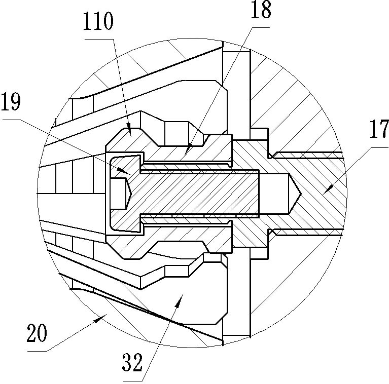
[0074] The difference between this embodiment and Embodiment 1 is that in Embodiment 1, the sleeve-shaped main body 18 of the slider 15 is sheathed on the connecting column 17 in a radially floating manner, while in this embodiment, the sleeve-shaped main body 18 and The connecting column 17 is positioned and matched in the radial direction, relying on the slight deformation of the petal-shaped claw body 32 to avoid the problem of over-positioning. Of course, in other implementations, the slider 15 can also be a single part.

Embodiment 4

[0076] The difference between this embodiment and Embodiment 1 is that both sides of the large-diameter part of the slider 15 in Embodiment 1 are cylindrical surfaces, while in this embodiment, the large-diameter part of the slider 15 is formed by a sleeve-shaped main body 18 The outer flange of the outer flange is formed, and the front end surface of the outer flange is used to axially stop and cooperate with the petal-shaped main body on the collet pulling claw 30 .


PUM


Abstract

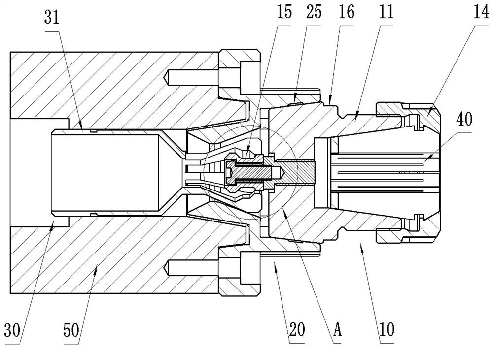
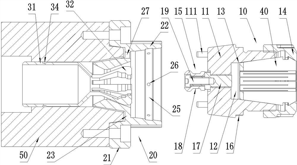
The invention relates to a workpiece quick-change tool for a lathe. The workpiece quick-change tool for the lathe comprises a collet chuck clamp, a main shaft connecting base and a chuck pull claw, the collet chuck clamp comprises a collet chuck, a collet chuck nut and a pull head, and the collet chuck nut is connected to the front end of the collet chuck in a threaded manner and used for pressingan elastic collet chuck to a positioning inner conical surface in the screwing process; the pull head is arranged on the rear side of the collet chuck; the main shaft connecting base comprises a chuck positioning hole, the collet chuck is provided with an outer conical surface, and the outer conical surface of the collet chuck is matched with the chuck positioning hole in shape, so that the collet chuck is positioned; the chuck pull claw comprises a pull rod connecting structure arranged at the rear end of the chuck pull claw and a petal-shaped claw body; and the radial outer side face of thepetal-shaped claw body has taper and faces the inclined rear portion, and the radial outer side face is used for enabling the petal-shaped claw body to shrink in the radial direction to hold the pullhead and pull the pull head backwards when the chuck pull claw moves backwards. According to the scheme, the problems that in the prior art, a lathe occupies long time to load and unload workpieces,and production efficiency is affected are solved.

Description

technical field [0001] The invention relates to a workpiece quick-changing tool for a lathe. Background technique [0002] The utilization rate and processing efficiency of lathes are important factors that enterprises need to consider in production. At present, elastic collet is a kind of common clamping tool in lathe processing, and a kind of spring collet disclosed for example CN209303753U, this collet is a kind of pull-type collet, is used for clamping when the lathe pull bar is pulled back , when used in conjunction with elastic collets, it can achieve a larger applicable range of workpiece specifications. [0003] The above-mentioned collet includes a collet seat, which is fixed on the end face of the lathe spindle, and the collet seat is provided with a collet, and the collet fixture is connected with the hydraulic pull rod or pneumatic pull rod on the lathe through the connecting cylinder, and the pull rod During the action, the collet fixture can be driven to move...

Claims


Application Information

Patent Timeline
Patent Type & Authority Applications(China)
IPC IPC(8): B23B31/20
CPCB23B31/20
Inventor 戚晓楠孙先海赵光裕陈然赵俊杰董方昱胡浩闫泽旺娄郑君高振
Owner HENAN AEROSPACE HYDRAULIC & PNEUMATIC TECH
Learn More