
Power converter and current comparison feedback circuit

A power converter and current comparison technology, which is applied in the directions of measuring current/voltage, adjusting electric variables, measuring electric variables, etc., can solve the problems of high power loss detection accuracy, etc., and achieve the goals of saving memory, improving processing efficiency, and low power loss Effect

Active Publication Date: 2021-05-14
HUAYUAN SEMICON SHENZHEN LTD
View PDF4 Cites 0 Cited by
  • Summary
  • Abstract
  • Description
  • Claims
  • Application Information

AI Technical Summary

Problems solved by technology

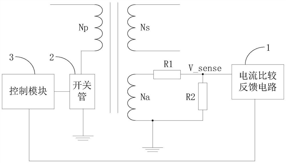
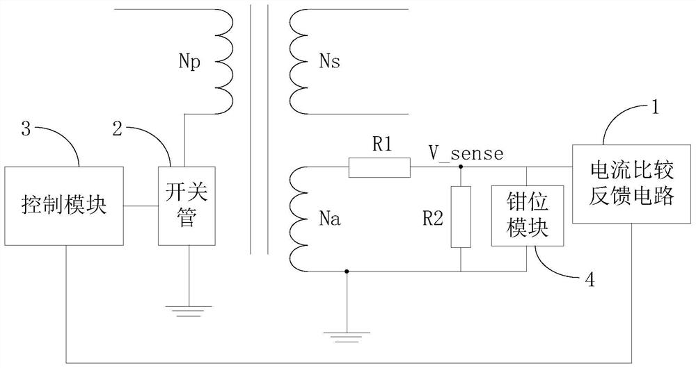
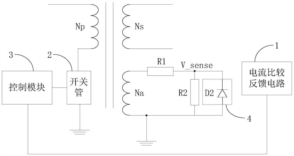
[0004] The invention provides a power converter and a current comparison feedback circuit to solve the problems of large power loss and detection accuracy of the detection part

Method used


Image

  • Power converter and current comparison feedback circuit
  • Power converter and current comparison feedback circuit
  • Power converter and current comparison feedback circuit

Examples


Embodiment Construction

[0121] The following will clearly and completely describe the technical solutions in the embodiments of the present invention with reference to the accompanying drawings in the embodiments of the present invention. Obviously, the described embodiments are only some, not all, embodiments of the present invention. Based on the embodiments of the present invention, all other embodiments obtained by persons of ordinary skill in the art without making creative efforts belong to the protection scope of the present invention.

[0122] The terms "first", "second", "third", "fourth", etc. (if any) in the description and claims of the present invention and the above drawings are used to distinguish similar objects and not necessarily Describe a specific order or sequence. It is to be understood that the data so used are interchangeable under appropriate circumstances such that the embodiments of the invention described herein can be practiced in sequences other than those illustrated or...


PUM


Abstract

The present invention provides a power converter and a current comparison feedback circuit, wherein the current comparison feedback circuit can be used to: form and maintain a reference current, the reference current is based on the first The first current of the resistor is determined; when the switch tube is in the off state, the second current of the first resistor is collected, and according to the comparison result between the reference current and the second current, it is sent to the control The module sends a feedback signal, so as to use the feedback signal to indicate whether the voltage at both ends of the switch tube enters a target range, and the target range matches the 0V voltage.

Description

technical field [0001] The invention relates to the field of circuit detection, in particular to a power converter and a current comparison feedback circuit. Background technique [0002] In the switching power supply converter, taking the flyback converter as an example, its core components may include, for example, a switch tube and a transformer, and the switch tube is connected in series with the primary winding of the transformer. The switch tube is controlled by the control module. In order to realize the control of the switch tube , and other possible control requirements, it is necessary to detect the source-drain voltage of the switch tube. Among them, it is necessary to detect whether the source-drain voltage of the switch tube is close to 0V, and then judge whether to turn on the switch tube according to the detection result, and realize ZVS (Zero Voltage Switching). By this method, the purpose of reducing the turn-on loss can be achieved. [0003] In the existin...

Claims


Application Information

Patent Timeline
Patent Type & Authority Patents(China)
IPC IPC(8): H02M1/08H02M3/335G01R19/175
CPCH02M1/08H02M3/33561G01R19/175H02M1/0009H02M1/0058Y02B70/10
Inventor 郭春明李盛峰
Owner HUAYUAN SEMICON SHENZHEN LTD
Learn More