


Quick Research
Generate reliable direction feasibility study reports for your R&D in just a few steps.

Technical Q&A
Discover and master advanced knowledge NOW. Basics, ideas, possibilities, all at once.

Find Solutions
As an expert in R&D theories, this can generate solutions to your technical problems instantly.

Evaluate Feasibility
Analyze your overall solution with one click, know your potential R&D risks in advance.

Monitor Landscape
Get weekly tech updates, stay abreast of the latest tech innovations and key insights.
Power cable protection tube
A power cable and cable protection technology, which is applied in the field of power cables, can solve the problems of reducing the use effect of the protective tube, failure of the protective effect of the protective tube, and potential safety hazards.
- Summary
- Abstract
- Description
- Claims
- Application Information
AI Technical Summary
Problems solved by technology
Method used
Image

Examples
Embodiment 1
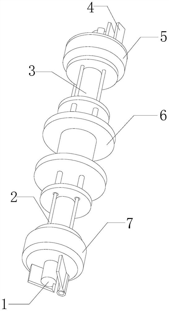
[0032] see figure 1 , the present invention provides a technical solution: a power cable protection tube, the structure of which includes a connection port 1, a telescopic device 2, a sleeve 3, a sealing device 4, a cable protection shell 5, a chuck 6, and a terminal 7. The connection port 1 is fixedly connected with the terminal 7, the terminal 7 is fixedly installed on the front end of the sleeve 3, the sleeve 3 is provided with a telescopic device 2, and the inner wall of the telescopic device 2 is closely attached to the outer wall of the sleeve 3 The sleeve 3 is set inside the cable protection shell 5, the front end of the cable protection shell 5 is provided with a terminal 7, and the inside of the cable protection shell 5 is provided with a sealing device 4, and the sealing device 4 is closely attached to the On the inner wall of the cable protection case 5, a chuck 6 is provided in the middle of the cable protection case 5, the chuck 6 is inlaid with the cable protect...
Embodiment 2
[0042] see figure 1 , the present invention provides a technical solution: a power cable protection tube, the structure of which includes a connection port 1, a telescopic device 2, a sleeve 3, a sealing device 4, a cable protection shell 5, a chuck 6, and a terminal 7. The connection port 1 is fixedly connected with the terminal 7, the terminal 7 is fixedly installed on the front end of the sleeve 3, the sleeve 3 is provided with a telescopic device 2, and the inner wall of the telescopic device 2 is closely attached to the outer wall of the sleeve 3 The sleeve 3 is set inside the cable protection shell 5, the front end of the cable protection shell 5 is provided with a terminal 7, and the inside of the cable protection shell 5 is provided with a sealing device 4, and the sealing device 4 is closely attached to the On the inner wall of the cable protection case 5, a chuck 6 is provided in the middle of the cable protection case 5, the chuck 6 is inlaid with the cable protect...
PUM
 Abstract
Description
Claims
Application Information
 - R&D Engineer
- R&D Manager
- IP Professional
- Industry Leading Data Capabilities
- Powerful AI technology
- Patent DNA Extraction
Browse by: Latest US Patents, China's latest patents, Technical Efficacy Thesaurus, Application Domain, Technology Topic, Popular Technical Reports.
© 2024 PatSnap. All rights reserved.Legal|Privacy policy|Modern Slavery Act Transparency Statement|Sitemap|About US| Contact US: help@patsnap.com