
Low-voltage line detection terminal for realizing automatic topology identification based on XML file

A low-voltage line and detection terminal technology, which is applied in the field of low-voltage lines, can solve the problems of not knowing how to correct errors, complicated work, and high participation, and achieve the effects of preventing artificial modification, convenient timely maintenance, and convenient identification

Active Publication Date: 2020-10-30
珠海市中山电力设备有限公司 +1
View PDF5 Cites 3 Cited by
  • Summary
  • Abstract
  • Description
  • Claims
  • Application Information

AI Technical Summary

Problems solved by technology

This kind of recording method requires too much human participation, and the work is complicated and easy to make mistakes. After making mistakes, we don’t know how to correct them. We need a processing method that automatically matches our own name and address, which can be automatically generated without manual records, so that The automatically generated topology automatically generates the device name

Method used


Image

  • Low-voltage line detection terminal for realizing automatic topology identification based on XML file
  • Low-voltage line detection terminal for realizing automatic topology identification based on XML file

Examples


Embodiment 1

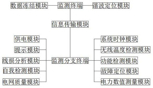
[0035] see figure 1 , 2, a low-voltage line detection terminal that realizes automatic topology recognition based on XML files, including monitoring terminal, harmonic positioning module, data freezing module, information transmission module, monitoring branch terminal, power supply module, prompt module, line loss analysis module, self-detection module, Power grid quality module, power calculation module, system clock module, wireless temperature detection module, function detection module, fault location module and power value measurement module, the monitoring terminal is respectively connected to the data freezing module, harmonic location module and Information transmission module, monitoring branch terminals are respectively connected to power supply module, prompt module, line loss analysis module, self-test module, power grid quality module, power calculation module, system clock module, wireless temperature detection module, function detection through cable, wireless ...

Embodiment 2

[0046] see figure 1 , a low-voltage line detection terminal that realizes automatic topology recognition based on XML files, including monitoring terminal, harmonic positioning module, data freezing module, information transmission module, monitoring branch terminal, power supply module, prompt module, line loss analysis module, self-detection module, Power grid quality module, power calculation module, system clock module, wireless temperature detection module, function detection module, fault location module and power value measurement module, the monitoring terminal is respectively connected to the data freezing module, harmonic location module and Information transmission module, monitoring branch terminals are respectively connected to power supply module, prompt module, line loss analysis module, self-test module, power grid quality module, power calculation module, system clock module, wireless temperature detection module, function detection through cable, wireless and ...


PUM


Abstract

The invention discloses a low-voltage line detection terminal for realizing automatic topology identification based on an XML file. The system comprises a monitoring terminal, a harmonic positioning module, a data freezing module, an information transmission module, a monitoring branch terminal, a power supply module, a prompt module, a line loss analysis module, a self-detection module, a power grid quality module, an electric energy calculation module, a system clock module, a wireless temperature detection module, a function detection module, a fault positioning module and an electric powernumerical value measurement module. The monitoring terminal is connected with the data freezing module, the harmonic positioning module and the information transmission module through cables, wireless and networks respectively, and the monitoring branch terminal is connected with the power supply module, the prompt module, the line loss analysis module, the self-detection module, the power grid quality module and the electric energy calculation module through cables, wireless and networks respectively. The low-voltage line detection terminal for realizing the automatic topology identificationbased on the XML file has the advantages of reducing the participation degree of people, being simple in work and being rapid in problem and error correction.

Description

technical field [0001] The invention relates to the technical field of low-voltage lines, in particular to a low-voltage line detection terminal for realizing automatic topology identification based on XML files. Background technique [0002] At present, when implementing the electrical topology in the station area, it is necessary to correspond to the name of each level. How is it done? The first step is to set the address of the device layer, and use a computer or other tools to record the corresponding relationship between the address and the device name; second. The first step is to form all the device addresses into the interconnection address, and then report all the interconnection addresses to the intelligent gateway, and the intelligent gateway will upload the information to the master station; the third step is to determine the addresses of the adjacent two layers, and after all the adjacent two-layer addresses are determined Report their respective hierarchical re...

Claims


Application Information

Patent Timeline
Patent Type & Authority Applications(China)
IPC IPC(8): G01R31/08G01R31/00G01R19/165G01D21/02H02J13/00
CPCG01D21/02G01R19/165G01R31/00G01R31/085H02J13/00002H02J13/00016Y02B90/20Y04S10/52Y04S40/124
Inventor 伍永超金肇光慕容建辉陈楷周永文郭卫东陈周辉
Owner 珠海市中山电力设备有限公司
Learn More