
A Determination Method of Optimal Demodulation Frequency Band for Fault Signature Enhancement

A technology of fault characteristic frequency and fault characteristics, which is applied in the testing of mechanical components, testing of machine/structural components, instruments, etc., can solve the problems of low accuracy of fault diagnosis, limited anti-interference ability, low calculation efficiency, etc., to achieve The effect of good suppression ability, intuitive distribution and high calculation efficiency

Active Publication Date: 2021-05-07
BEIHANG UNIV +1
View PDF9 Cites 0 Cited by
  • Summary
  • Abstract
  • Description
  • Claims
  • Application Information

AI Technical Summary

Problems solved by technology

Although the blind source analysis method has a strong ability to suppress noise, it is easily affected by complex interference components in the signal and has poor robustness; while the existing targeted analysis methods often require repeated trial and error, and the calculation efficiency is low
In addition, although the targeted analysis method is more robust than the blind source analysis method, it is still susceptible to the influence of non-fault periodic interference components, especially for cyclostationary signals. Capability is limited, and the accuracy of fault diagnosis is not high

Method used


Image

  • A Determination Method of Optimal Demodulation Frequency Band for Fault Signature Enhancement
  • A Determination Method of Optimal Demodulation Frequency Band for Fault Signature Enhancement
  • A Determination Method of Optimal Demodulation Frequency Band for Fault Signature Enhancement

Examples


Embodiment Construction

[0041] In order to better understand the technical solutions of the present invention, the present invention will be described in detail below in conjunction with the accompanying drawings and embodiments.

[0042] Taking the locomotive rolling bearing fault detection test bench in a depot as an example, the bearing fault location is at the inner ring / outer ring, and the fault type is peeling. Bearing specific parameters: A certain type of roller bearing, the pitch diameter of the bearing is 180mm, the number of bearing rollers is 20, the radius of the bearing rollers is 23.775mm, and the contact angle is 9°.

[0043] Such as figure 1 As shown, the extraction method of rolling bearing fault features based on equal-angle double sampling includes the following steps:

[0044] Step 1: Adsorb the vibration acceleration sensor on the bearing seat of the rolling bearing, perform high-frequency sampling, and at a stable speed f 0 According to the sampling frequency fs, intercept th...


PUM


Abstract

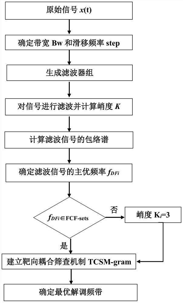
The present invention provides a method for determining the optimal demodulation frequency band for fault feature enhancement, which includes the following steps: Step 1, obtaining the original signal x(t); Step 2, calculating the fault feature frequency and setting a sliding filter bank; Step 3: Generate the fault feature confidence interval FCF‑sets; Step 4: Use the sliding filter bank to filter x(t), and calculate the kurtosis value K of each filtered signal i and the envelope spectrum of the filtered signal; then the main frequency f of the envelope spectrum of the filtered signal is obtained DFi ;according to f DFi to K i Perform an assignment operation to obtain a new filtered signal kurtosis K new ; Step 5: According to K new , f DFi As well as FCF‑sets, a targeted coupling screening mechanism TCSM‑gram is built, and the kurtosis maximum value K in the confidence interval of each fault feature is newj The corresponding center frequency is used as the optimal center frequency, and finally the optimal demodulation frequency band for fault feature enhancement is obtained. The invention has strong diagnostic ability for complex faults and high robustness; adopts a targeted coupling screening mechanism, and the information display is complete and intuitive.

Description

technical field [0001] The invention relates to the technical field of rolling bearing fault diagnosis, in particular to a method for determining an optimal demodulation frequency band for fault feature enhancement. Background technique [0002] Rolling bearings, gear trains, etc. are important parts of rotating machinery, and their stable operation is crucial to the normal operation of the entire mechanical system. Therefore, it is of great significance to carry out health monitoring and fault diagnosis on rolling bearings and gear trains. As an effective fault diagnosis method, resonance demodulation has been widely used in the fault diagnosis of rotating machinery. How to determine the optimal demodulation frequency band in the presence of interference such as strong background noise, so as to effectively enhance the fault characteristics, and then Accurately judging the health status of rotary machinery has been extensively studied by many scientific researchers. [00...

Claims


Application Information

Patent Timeline
Patent Type & Authority Patents(China)
IPC IPC(8): G01M13/045G01M13/028G01M13/021
CPCG01M13/021G01M13/028G01M13/045
Inventor 林京闫畅
Owner BEIHANG UNIV
Learn More