Construction method of sandy soil geological cut-off wall

A construction method and technology of anti-seepage wall, applied in sheet pile wall, foundation structure engineering, construction, etc., can solve the problems of low construction efficiency and poor construction quality, etc.

Active Publication Date: 2020-10-30
广东志讯建设工程有限公司
View PDF7 Cites 0 Cited by
  • Summary
  • Abstract
  • Description
  • Claims
  • Application Information

AI Technical Summary

Problems solved by technology

[0005] In order to solve the existing problems of low construction efficiency and poor construction quality in the construction of anti-seepage walls under sandy soil, the present invention provides a construction method for anti-seepage walls on sandy soil, which uses the good permeability of sandy soil itself The characteristics of the anti-seepage wall are combined with the grouting method to finally form a cut-off wall formed by mixing sand and cement, although the wall strength of the cut-off wall is lower than that of the existing construction method (there is no reinforcement or gravel in the cut-off wall equal matrix, resulting in its strength lower than the existing cut-off wall made of cement concrete), but the construction is simple, the efficiency is high, and the seepage-proof effect is good

Method used


Image

  • Construction method of sandy soil geological cut-off wall
  • Construction method of sandy soil geological cut-off wall

Examples


Embodiment 1

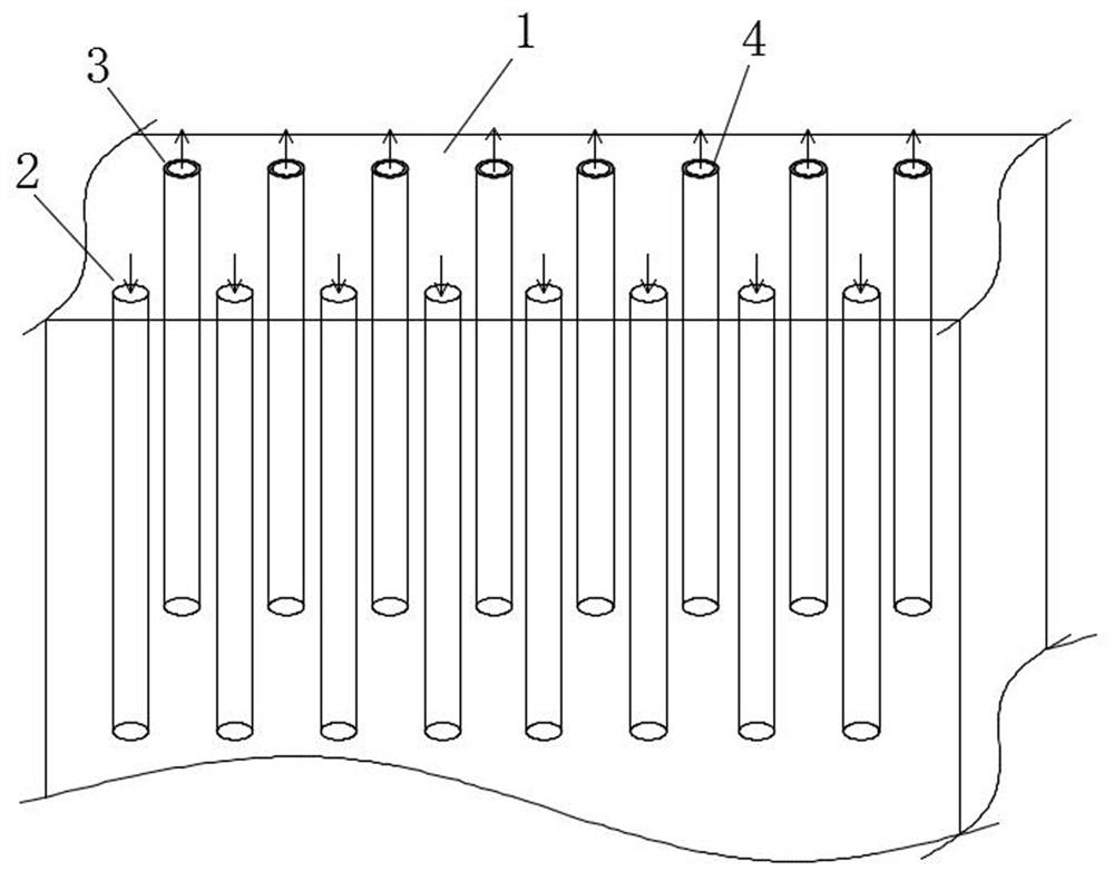
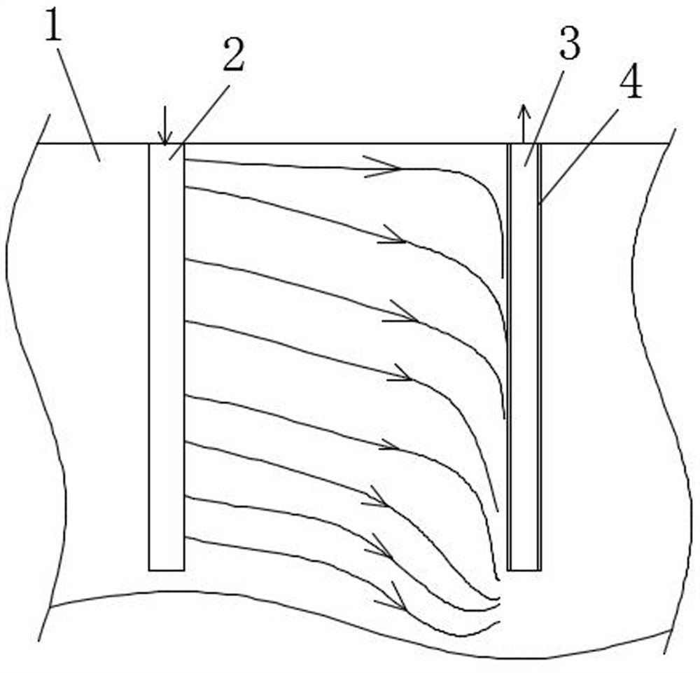
[0034] Such as figure 1 with 2 Shown, a kind of construction method of sandy ground anti-seepage wall, comprises the following steps:

[0035] 1) Along the length direction of the planned cut-off wall, draw the width boundary of the cut-off wall on the sandy soil layer 1, thus forming two parallel preset lines;

[0036] 2) Drill holes symmetrically on two parallel preset lines to form a row of grouting holes 2 and a row of negative pressure holes 3. The depth of the grouting holes 2 and negative pressure holes 3 is equal to the The height of the seepage wall, the distance between the two is the width of the cut-off wall, and each grouting hole 2 and a negative pressure hole 3 are correspondingly distributed along the center of the cut-off wall width, forming a grouting hole group;

[0037] 3) Insert a PC tube 4 with both ends open in each negative pressure hole 3, and the outer wall of the PC tube 4 has the same diameter as the inner wall of the negative pressure hole 3;

...

Embodiment 2

[0047] This example is an improvement made on the basis of Example 1. Its main body is the same as Example 1. The improvement is that the diameters of the grouting hole 2) and the negative pressure hole 3) are both 0.1m , the spacing between two adjacent grouting holes 2) or two adjacent negative pressure holes 3) is 0.5m, and in any group of grouting holes, the spacing between grouting holes 2) and negative pressure holes 3) is 0.8m.

Embodiment 3

[0049] This embodiment is another improvement made on the basis of embodiment 1. Its main body is the same as that of embodiment 1. The improvement is that in step 9), after the grouting construction of the entire anti-seepage wall is completed, Carry out hole-repairing grouting again, the operation of described hole-repairing grouting is: the operation of described hole-repairing grouting is: after construction finishes seven days, first measure the wall-forming quality of anti-seepage wall with the georadar of non-destructive testing, for For areas where the strength does not meet the set requirements, repeat the grouting construction process of steps 5)-8) and test again after seven days until it meets the requirements; for areas where the strength meets the set requirements, pour grouting holes 2 and negative pressure holes 3 and PC pipe 4 are filled and sealed with cement slurry to prevent sundries and rainwater from washing out.


PUM


Abstract

The invention provides a construction method of a sandy soil geological cut-off wall. A planned position of the cut-off wall is drilled along two sides of the width, so that a row of grouting holes and a row of negative pressure holes are formed; a PC pipe with two opened ends is inserted into each negative pressure hole; then at the same time during grouting into each grouting hole, and a negative pressure is applied to the upper end of the PC pipe in the negative pressure hole corresponding to the grouting hole being grouted, so that guide force is formed between the grouting hole and the negative pressure hole, and paste in the grouting hole penetrates clearance in sandy soil under effects of the guide force and gets cured gradually to form the underground cut-off wall. The method disclosed by the invention has the beneficial effects that the characteristic of good penetration performance of sandy soil geology is utilized, the sandy soil is coordinated with the grouting method, thecut-off wall with mixing of the sandy soil and cement is finally formed, construction is easy, efficiency is high, and anti-seepage effects are good; and the paste forms the wall under guidance of theguide force, a sandy soil stratum is cured by the cement paste, and the characteristic of a high permeability rate of the sandy soil is effectively utilized, so that the underground cut-off wall is built without disturbance of the stratum, and the method is beneficial for environmental protection.

Description

technical field [0001] The invention relates to an anti-seepage wall in the field of construction engineering, in particular to a construction method for an anti-seepage wall on sandy ground. Background technique [0002] The anti-seepage wall is widely used in the construction of the underground part of the building because of its strong structural stability, good anti-seepage performance, limited construction by geological conditions, and wide range of uses. The construction of the anti-seepage wall in the prior art generally adopts ground drilling and grouting to form a section of wall, then drills and grouts at a certain distance to form another section of wall, and finally between two adjacent sections of wall Drill holes and inject grouting to connect the separated walls to form a continuous anti-seepage wall. [0003] However, under the sandy soil geological conditions, due to the large particles of the sandy soil layer and the lack of cementation between each other,...

Claims


Application Information

Patent Timeline
IPC IPC(8): E02D19/18E02D5/18
CPCE02D5/18E02D19/18
Inventor 袁延召白哲陈卓朱晗宇范哲杨铭斐翟聚云李锐铎
Owner 广东志讯建设工程有限公司
Why Eureka
Try Eureka