Control method of washing machine and washing machine
A control method and washing machine technology, applied to the control device of washing machines, other washing machines, washing devices, etc., can solve the problems of increasing spray rinsing, rinsing lint, and dirt, and achieve the effect of removing foam
- Summary
- Abstract
- Description
- Claims
- Application Information
AI Technical Summary
Problems solved by technology
Method used
Image
Examples
specific Embodiment approach 1
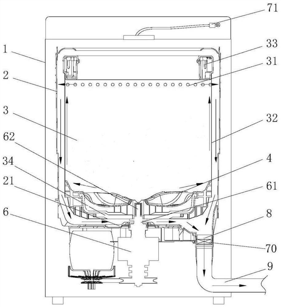
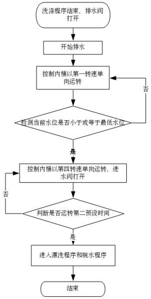
[0033] Embodiment 1: During the drainage process, the redistribution stage is executed, the inner tub 3 is controlled to run in one direction at the first rotational speed, and the spraying stage is executed after the drainage is completed. like figure 2As shown in the control flow chart, the redistribution stage is as follows: after washing, the drain valve is opened, the washing machine starts to drain water, and at the same time, the inner tub 3 is controlled to run in one direction at a first rotational speed, and the first rotational speed can be determined according to The weight of the load in the inner tub 3 is used for setting, and the first rotational speed is proportional to the weight of the load in the inner tub 3 . The load in the inner barrel 3 is separated from the center of the inner barrel 3 within the size of the first rotational speed, and the center of the inner barrel 3 forms a cavity preferably. Loads with different weights correspond to different firs...
specific Embodiment approach 2
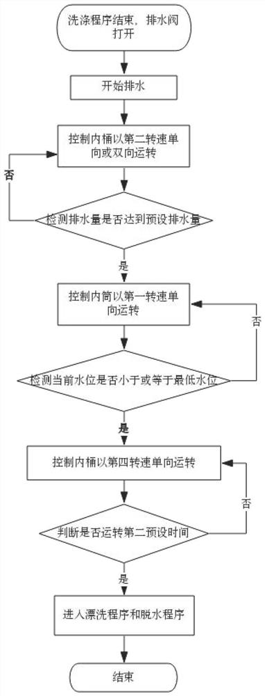
[0036] Specific embodiment 2: The difference between this embodiment and specific embodiment 1 is: before performing the redistribution stage, it also includes: controlling the inner bucket 3 to run in one direction or two directions at the second speed during the drainage process, when detecting the drainage in the inner bucket 3 When the preset displacement is reached, the second speed running state ends, such as figure 2 The control flow diagram shown. The size of the second rotating speed should be such that the water in the inner tub 3 can be slowly thrown out from the dehydration hole 31 above, and the second rotating speed is set according to the height of the water level in the inner tub 3 . The first rotating speed is inversely proportional to the height of the water level in the inner tub 3 . The rotation speed corresponding to each water level is recorded in the controller, the rotation speed range is 200-400 rpm, and the second rotation speed is greater than or e...
specific Embodiment approach 3
[0039] Embodiment 3: After the drainage is completed, the redistribution stage is executed, and the inner tub is controlled to run in one direction at the third rotational speed. After the inner tub 3 runs for the first predetermined time, the spraying stage is executed. like image 3 The control flow chart shown is specifically: after the washing is finished, the drain valve is opened, and when the water level detection device detects that the current water level is less than or equal to the minimum water level, it is considered that the water in the inner tub 3 has been drained. The minimum water level is used to judge whether there is water in the inner bucket 3, and the minimum water level is stored in the controller, preferably 0≤minimum water level<5mm. Since the inner tub 3 is not running during the drainage process, no cavity is formed in the inner tub 3. Therefore, after the drainage is completed, it is necessary to control the inner tub 3 to run at a third speed so t...
PUM
 Abstract
Description
Claims
Application Information
 - R&D
- Intellectual Property
- Life Sciences
- Materials
- Tech Scout
- Unparalleled Data Quality
- Higher Quality Content
- 60% Fewer Hallucinations
Browse by: Latest US Patents, China's latest patents, Technical Efficacy Thesaurus, Application Domain, Technology Topic, Popular Technical Reports.
© 2025 PatSnap. All rights reserved.Legal|Privacy policy|Modern Slavery Act Transparency Statement|Sitemap|About US| Contact US: help@patsnap.com


