
Pulse feeder

A feeder and pulsation generator technology, applied in conveyors, conveyor objects, transportation and packaging, etc., can solve the problems of increased loss, large uniformity of feeding speed, large contact surface between powder and hot air flow, etc. The effect of reducing the contact area, protecting the feeding hopper, and reducing the flying loss

Active Publication Date: 2021-08-13
江西南方稀土高技术股份有限公司
View PDF2 Cites 0 Cited by
  • Summary
  • Abstract
  • Description
  • Claims
  • Application Information

AI Technical Summary

Problems solved by technology

[0003] Manual feeding means that the operator uses a metal spoon to load the material and then pours it into the rare earth molten salt electrolytic cell. This method is labor-intensive, and the uniformity of the feeding speed is greatly affected by human factors and is unstable.
[0004] The machine vibrating feeding is through the machine vibrating feeding process that the powder continuously falls into the melt surface of the electrolytic cell. The falling process of the powder runs in reverse with the rising hot air flow. Because the powder is scattered and falls, the contact surface between the powder and the hot air flow is large. Cause powder to fly, increase loss and increase cost
[0005] During the high-level free-fall feeding process, the powder continuously flows to the melt surface of the electrolytic cell through the metal pipe. The powder is flying, which increases the loss; and if the metal pipe flow mouth is immersed in the melt surface to a certain depth, it will cause corrosion of the metal pipe or block the pipe due to the sintering of the contact flour material and the splash of the solution, increasing the consumption of the metal pipe or increasing equipment maintenance costs

Method used


Image

  • Pulse feeder
  • Pulse feeder
  • Pulse feeder

Examples


Embodiment

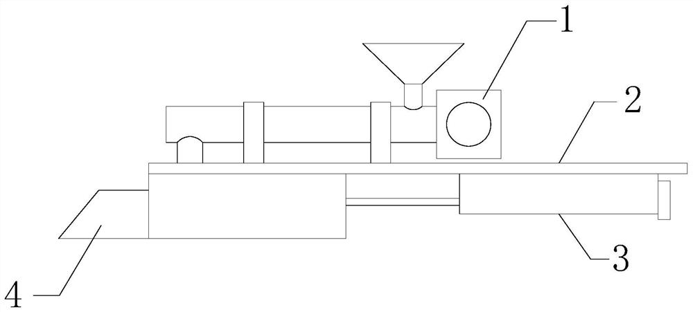
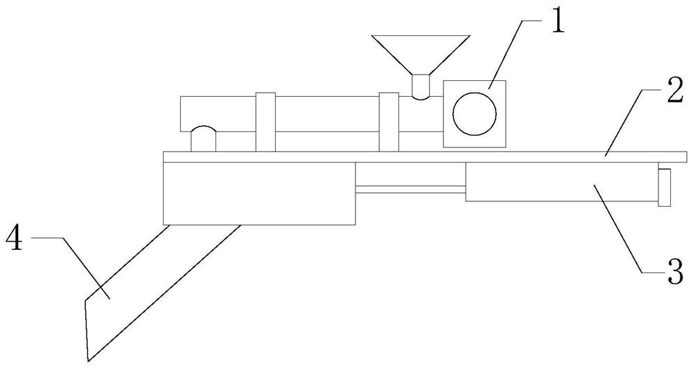
[0026] see Figure 1-Figure 2 , a pulsating feeder, including an installation platform 2, a screw feeding mechanism 1, a pulsation generator 3 and a hopper, the screw feeding mechanism 1 is arranged on the top of the installation platform 2, and the pulsation generator 3 is arranged on the installation platform 2 At the bottom, the feeding hopper 4 is used to receive the material conveyed by the screw feeding mechanism 1 and transfer it into the molten pool of the electrolytic furnace, and the feeding hopper is driven by the pulse generator 3 to move.

[0027] As an improved solution of the above solution, the screw conveying mechanism 1 can adopt one of belt conveyor, bucket conveyor, buried scraper conveyor, vibrating conveyor or pneumatic conveyor.

[0028] As an improvement on the above scheme, see image 3 The screw conveying mechanism 1 includes a hopper 103, a rotating shaft blade 105 and a first motor 101, and the top of the chute 103 is provided with an upper hopper ...


PUM


Abstract

The invention provides a pulsating feeder, comprising an installation platform, a screw feeding mechanism, a pulsation generator and a feeding head, the screw feeding mechanism is arranged on the top of the installation platform, the pulsation generator is arranged on the bottom of the installation platform, and the The feeding hopper is used to receive the material conveyed by the screw feeding mechanism and transfer it into the molten pool of the electrolytic furnace, and the feeding head is driven by the pulse generator. The contact area between the powder and the rising hot air flow reduces the flying loss of the powder. At the same time, the feeding hopper is a certain distance away from the electrolysis furnace mouth and does not come into contact with the high-temperature molten salt, which can protect the feeding hopper.

Description

technical field [0001] One or more embodiments of this specification relate to the field of rare earth molten salt electrolysis equipment, especially to a pulse feeder. Background technique [0002] In the rare earth molten salt electrolysis process, there are three main methods of feeding materials into the electrolytic cell: manual feeding, machine vibration feeding, screw feeding and high-level free-fall feeding. [0003] Manual feeding means that the operator uses a metal spoon to load the material and then pours it into the rare earth molten salt electrolytic cell. This method is labor-intensive, and the uniformity of the feeding speed is greatly affected by human factors and is unstable. [0004] The machine vibrating feeding is through the machine vibrating feeding process that the powder continuously falls into the melt surface of the electrolytic cell. The falling process of the powder runs in reverse with the rising hot air flow. Because the powder is scattered and...

Claims


Application Information

Patent Timeline
Patent Type & Authority Patents(China)
IPC IPC(8): C25C3/34C25C7/00B65G33/26B65G33/24B65G47/74
CPCB65G33/24B65G33/26B65G47/74B65G2201/04C25C3/34C25C7/00
Inventor 邝国春温惠忠张旭熙毛建辉林秀龙郭连平余党华刘振龙刘鑫苏汤勇温惠荣
Owner 江西南方稀土高技术股份有限公司
Learn More