Metal mask assembly, OLED display panel and display device

A metal mask and mask technology, which is applied in metal material coating process, electrical components, electrical solid devices, etc., can solve the problem of poor adhesion between metal masks and glass substrates, and uneven pressure on metal masks. , uneven combing of the shielding plate, etc., to avoid poor evaporation, uniform force and good fit.

Active Publication Date: 2020-10-30
BOE TECH GRP CO LTD +1
View PDF10 Cites 2 Cited by
  • Summary
  • Abstract
  • Description
  • Claims
  • Application Information

AI Technical Summary

Problems solved by technology

[0002] Due to the current glass backplane preparation equipment and process, in OLED production, a glass substrate is evaporated along the extension direction of one of its long sides, and a glass substrate needs multiple evaporations to fully absorb the surface of the entire glass substrate. The same layer of film is evaporated completely. In order to ensure good evaporation of the evaporation area of ​​the glass substrate, the film layers of two adjacent evaporations have an overlapping area. Among them, in the mask plate assembly, the The width of the shielding plate is different from that of other shielding areas. In this way, during the evaporation process, the magnetic force received is different from that of the shielding plates in other areas, so that the combing of each shielding plate is not uniform, and the metal mask will be damaged. The uneven pressure of the plate (FMM) will easily lead to poor bonding between the metal mask plate and the glass substrate, and further problems such as poor evaporation

Method used


Image

  • Metal mask assembly, OLED display panel and display device
  • Metal mask assembly, OLED display panel and display device

Examples


Embodiment Construction

[0020] The following will clearly and completely describe the technical solutions in the embodiments of the present invention with reference to the accompanying drawings in the embodiments of the present invention. Obviously, the described embodiments are only some, not all, embodiments of the present invention. Based on the embodiments of the present invention, all other embodiments obtained by persons of ordinary skill in the art without making creative efforts belong to the protection scope of the present invention.

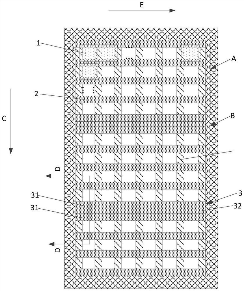
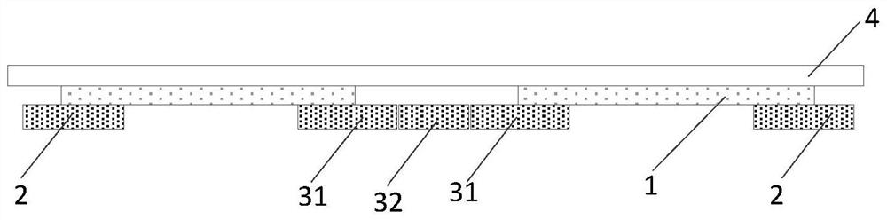
[0021] Such as figure 1 and figure 2 As shown, the embodiment of the present invention provides a metal mask assembly, including: a mask body, the mask body has figure 1 (direction C) shown in C) alternately distributed single evaporation area A and overlapping evaporation area B, the mask plate body includes a plurality of precision metal mask plates 1 distributed in an array, located in the single evaporation area and along the first The first transverse ...


PUM


Abstract

The invention relates to the technical field of display and discloses a metal mask assembly, an OLED display panel and a display device. The metal mask assembly comprises a mask body. The mask body comprises multiple fine metal masks distributed in array, first transverse sheltering plates located in one-time evaporation areas and arranged at intervals in a first direction and second transverse sheltering plates located in repeated evaporation areas. Each second transverse sheltering plate comprises two first sheltering sub-plates distributed in the first direction, wherein the dimension of the first sheltering sub-plate and the dimension of each first transverse sheltering plate are identical in the first direction. According to the metal mask assembly, the width of each first shelteringsub-plate and the width of each first transverse sheltering plate are identical, so that the pressure borne by the edge portions of each fine metal mask located between the corresponding first transverse sheltering plate and the corresponding first sheltering sub-plate is identical, and then the edge portions of the fine metal mask plates are evenly stressed; and in this way, it can be guaranteedthat the fine metal masks are well attached to a glass substrate, and poor evaporation is avoided.

Description

technical field [0001] The invention relates to the field of display technology, in particular to a metal mask assembly, an OLED display panel and a display device. Background technique [0002] Due to the current glass backplane preparation equipment and process, in OLED production, a glass substrate is evaporated along the extension direction of one of its long sides, and a glass substrate needs multiple evaporations to fully absorb the surface of the entire glass substrate. The same layer of film is evaporated completely. In order to ensure good evaporation of the evaporation area of ​​the glass substrate, the film layers of two adjacent evaporations have an overlapping area. Among them, in the mask plate assembly, the The width of the shielding plate is different from that of other shielding areas. In this way, during the evaporation process, the magnetic force received is different from that of the shielding plates in other areas, so that the combing of each shielding p...

Claims


Application Information

Patent Timeline
IPC IPC(8): C23C14/04C23C14/24H01L51/00H01L27/32
CPCC23C14/042C23C14/24H10K59/00H10K71/166
Inventor 高翔吕文旭伍青峰范博杨林魏立超
Owner BOE TECH GRP CO LTD
Why Eureka
Try Eureka