Multi-tonnage large-scale lifting device with lever push-pull structure

A lifting device and large-scale technology, applied in the direction of lifting devices, hoisting devices, etc., can solve the problems of equal quantity and speed, low product grade, and difficulty in borrowing power

Pending Publication Date: 2020-10-30
王昌佑
View PDF1 Cites 3 Cited by
  • Summary
  • Abstract
  • Description
  • Claims
  • Application Information

AI Technical Summary

Problems solved by technology

[0002] Disposable plastic catering utensils for daily use, such as disposable cups, bowls, plates, covers, boxes and other products, there are mainly two production methods for producing such disposable plastic catering utensils in the prior art. The first is to adopt The way of injection molding, although there are no corners of raw materials that can be fully utilized in injection molding production, there are problems such as expensive molds, long mold processing and debugging cycles, and easy to lose opportunities to seize the market, and the number and speed of each mold in injection molding production cannot match Sheet material air thermoforming cup making machine on par
The second way is to use a sheet thermoforming machine to punch out the mold. The appearance of the product prepared by this method is solid color without pattern, and the product grade is low. Even if the product is printed on a curved surface, the clarity and texture of the product cannot be compared with injection molding or in-mold labeling
Although this structure can convert the power of the electric servo drive mechanism into the action of opening and closing the mold, the multi-link opening and closing drive mechanism of this structure has a small lifting range and it is difficult to use force.
[0003] Therefore, in view of the existing problems in the prior art, especially for the problem of large travel and multiple lifts when opening the labeling mold in the thermoforming mold, it is urgent to provide a foldable lift with a large lift range and can be used to reduce the load. The driving mechanism is particularly important

Method used


Image

  • Multi-tonnage large-scale lifting device with lever push-pull structure
  • Multi-tonnage large-scale lifting device with lever push-pull structure
  • Multi-tonnage large-scale lifting device with lever push-pull structure

Examples


Embodiment 1

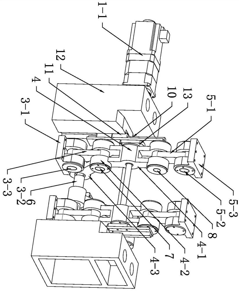
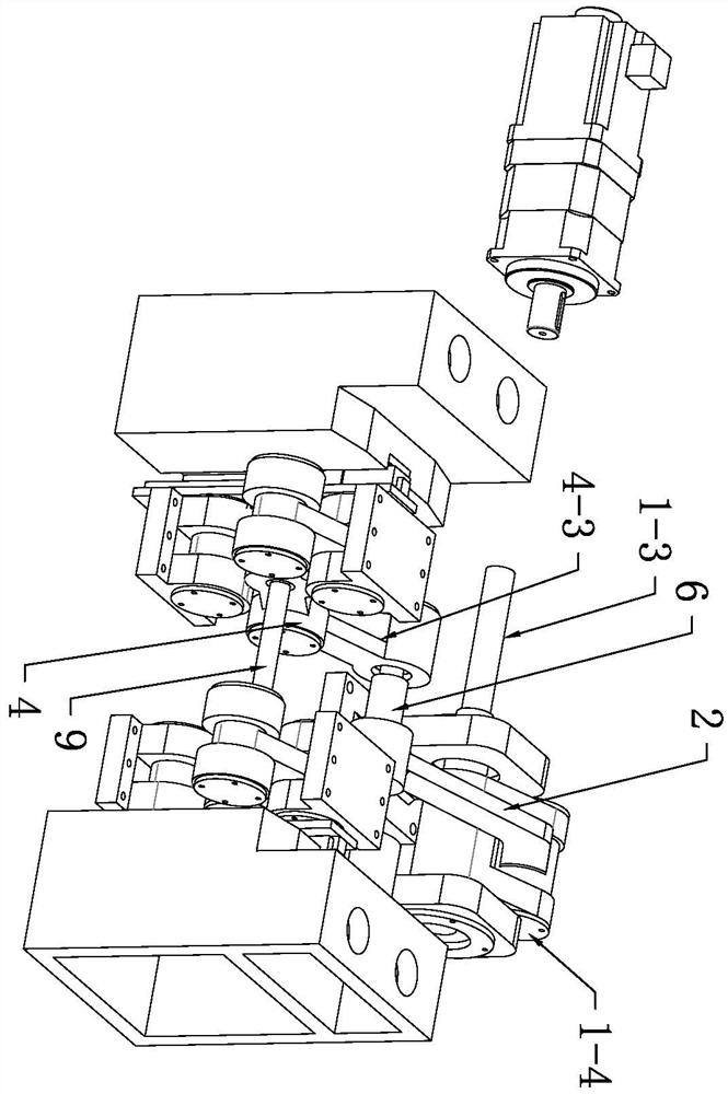
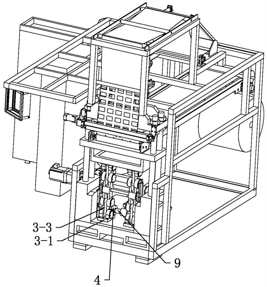
[0050] see Figures 1 to 5 The multi-tonnage large-scale lifting device of the lever push-pull structure of the present embodiment includes an upper rotating support base 5-3, a lower rotating support base 3-1, an upper lifting motion crank 5-1, a lower lifting motion crank 3-3, a positioning Lifting shaft, vertical lifting limit slider 10, lever pressing and pulling lifting crank 2, forward and reverse rotation driving crank 1-4, positioning and rotating slide lever crank 4, positioning lifting shaft 9 and push-pull drive mechanism, the push-pull drive mechanism is a servo motor 1-1, the servo motor 1-1 is equipped with a reducer 1-2, and the forward and reverse rotation driving crank 1-4 is fastened to the drive shaft 1-3 of the reducer 1-2.

[0051] In this embodiment, the lower end of the lower lifting crank 3-3 is relatively rotatably connected to the lower rotating support base 3-1 through a hinge shaft, and the upper end of the lower lifting crank 3-3 is hinged to the p...

Embodiment 2

[0056] The main technical solution of this embodiment is basically the same as that of Embodiment 1, and the features not explained in this embodiment are explained in Embodiment 1, and will not be repeated here. The difference between this embodiment and Embodiment 1 is that the forward and reverse rotation driving crank 1-4 can also be an eccentric wheel.

Embodiment 3

[0058] The main technical solution of this embodiment is basically the same as that of Embodiment 1, and the features not explained in this embodiment are explained in Embodiment 1, and will not be repeated here. see Image 6 , The difference between this embodiment and Embodiment 1 is that the push-pull drive mechanism includes a motor, a drive shaft 1-5, a driving gear 1-6, a rack 1-7 and a connecting piece 1-8, and the motor is equipped with a reducer , the drive shaft 1-3 of the reducer is used as the drive shaft 1-5 or the drive shaft 1-5 is connected with the drive shaft 1-3 of the reducer through a coupling. The motor drives the drive shaft 1-5 to rotate, the driving gear 1-6 is installed on the drive shaft 1-5 and rotates with the drive shaft 1-5, the gear and the rack 1-7 are engaged for transmission, and one end of the rack 1-7 is fixedly connected with Connecting piece 1-8, connecting piece 1-8 is relatively rotatably connected with the rear end of lever pressing a...


PUM


Abstract

The invention relates to a multi-tonnage large-scale lifting device with a lever push-pull structure. A vertical lifting limiting sliding part connected with a positioning lifting shaft is slidably arranged on a lifting sliding part fixed on a static supporting seat, and a central point of a hinge shaft connected with a lower rotating supporting seat, a central point of a positioning lifting shaftand a central point of a hinge shaft connected with an upper rotating supporting seat form a vertical lifting structure in a mode that the three points are always formed into one line. In combinationwith vertical lifting limiting, a hinge shaft point of the rotation radii in the forward and reverse directions of a rotating lifting crank and a lever hinge push-pull support point extending downwards are utilized, and transmission parts such as a lever push-pull crank and a forward and reverse rotation crank are connected, so that large-scale lifting is achieved. Compared with the prior art, the device only needs a very small rotation angle to rotate to vertical or rotating folding, and therefore the influence of the bending degree of a lever press-pull lifting crank is very small, and in the swing process of a positioning rotating sliding lever crank, an upper lifting motion crank performs rotating vertical lifting or horizontally-overturned folding lowering accordingly, so as to realize the linkage.

Description

technical field [0001] The invention relates to the technical field of compressed air thermoforming, in particular to a multi-tonnage large-scale lifting device with a lever push-pull structure. Background technique [0002] Disposable plastic catering utensils for daily use, such as disposable cups, bowls, plates, covers, boxes and other products, there are mainly two production methods for producing such disposable plastic catering utensils in the prior art. The first is to adopt The way of injection molding, although there are no corners of raw materials that can be fully utilized in injection molding production, there are problems such as expensive molds, long mold processing and debugging cycles, and easy to lose opportunities to seize the market, and the number and speed of each mold in injection molding production cannot match Sheet material air thermoforming cup making machine on a par. The second way is to use a sheet thermoforming machine to punch out the mold. Th...

Claims


Application Information

Patent Timeline
IPC IPC(8): B66F19/00B29C51/26
CPCB66F19/00B29C51/26
Inventor 王昌佑
Owner 王昌佑
Why Eureka
Try Eureka