Auxiliary frame and motor vehicle

A sub-frame and motor vehicle technology, applied in vehicle components, transportation and packaging, substructure, etc., can solve problems such as not satisfying light weight and smoothness, increasing the weight of the reducer, and large displacement

Pending Publication Date: 2020-10-30
启航汽车有限公司
View PDF0 Cites 0 Cited by
  • Summary
  • Abstract
  • Description
  • Claims
  • Application Information

AI Technical Summary

Problems solved by technology

[0003] In the prior art, the strength of the bottom plate is generally enhanced in the following ways: 1. The bottom plate is made of thicker steel plates, but this will directly increase the quality of the sub-frame, thus failing to meet the requirements for light weight and ride comfort ; 2. The bottom plate of the subframe is customized according to the specific shape of the motor and reducer, but this requires redesigning the bottom plate of the subframe according to the motor and reducer, which is not conducive to the modification of the motor vehicle; 3. Since the outer casing of the reducer directly accepts the wheel side load transmitted by the hub, the thickness of the outer casing of the reducer is increased to reduce the transmission of the wheel side load to the bottom plate, but this will significantly increase the weight of the reducer, while the gear of the reducer Due to the side load of the wheel, there is a large displacement, which is not conducive to gear meshing, which will also increase noise and reduce the service life of the gear

Method used


Image

  • Auxiliary frame and motor vehicle
  • Auxiliary frame and motor vehicle
  • Auxiliary frame and motor vehicle

Examples


no. 1 example

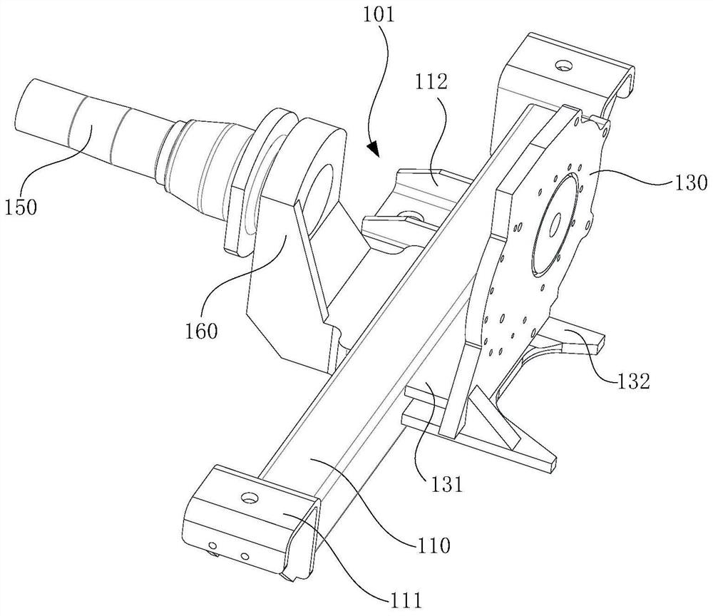
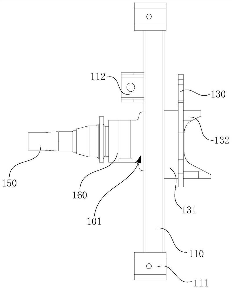
[0028] see figure 1 , which is a schematic structural view of a subframe 100 provided in the first embodiment of the present invention. The subframe 100 includes, for example, two longitudinal beams 110 oppositely arranged, two first cross beams 120, and two mounting brackets. 130 , the second beam 140 , two half-shaft sleeves 150 , and two wheel-side connectors 160 . Wherein, the two first beams 120 are connected between the two longitudinal beams 110 at intervals, the two installation frames 130 are respectively connected to opposite ends of the two first beams 120, and the second beam 140 is connected to the two installation frames 130 The two half shaft sleeves 150 are located on the sides of the two longitudinal beams 110 away from the two first cross beams 120 respectively, and the two wheel side connectors 160 are respectively connected to the two half shafts. Between the bushing 150 and the corresponding longitudinal beam 110 .

[0029] In order to facilitate a clear...

no. 2 example

[0043] The second embodiment of the present invention provides a motor vehicle (not shown in the figure), for example, the motor vehicle includes: a motor vehicle body and the sub-frame 100 as provided in the first embodiment. Wherein, the subframe 100 is installed to the frame of the vehicle body. Wherein, the motor vehicle body may be an existing motor vehicle, that is, the sub-frame 100 may be installed on the frame of an existing motor vehicle.

[0044] Specifically, see Figure 4 , the second mounting position 102 formed between the second beam 140, the two first beams 120 and the two mounting brackets 130 is used to install the wheel drive motor of the vehicle body; the two first mounting positions 101 are respectively used for The wheel drive reducer 170 of the motor vehicle body is installed; the axle sleeve 150 is connected to the wheel of the motor vehicle body. Further, the output shaft of the wheel drive motor is pivotally connected to the input shaft of the whee...


PUM


Abstract

The embodiment of the invention discloses an auxiliary frame and a motor vehicle. The auxiliary frame comprises two longitudinal beams which are oppositely arranged, the two first cross beams which are connected between the two longitudinal beams at intervals, two mounting frames which are connected with the two opposite ends of the front cross beam and the rear cross beam respectively, a second cross beam which is connected to the sides, far away from the two first cross beams, of the two mounting frames, two half shaft sleeves which are located on the sides, away from the two first cross beams, of the two longitudinal beams correspondingly, and two wheel side connecting pieces which are respectively connected between the two half axle sleeves and the corresponding longitudinal beams. According to the embodiment of the invention, the problems of low strength, complex structure and difficult modification of the auxiliary frame are effectively solved.

Description

technical field [0001] The invention relates to the technical field of motor vehicle accessories, in particular to a sub-frame and a motor vehicle. Background technique [0002] At present, the main way for a motor vehicle to realize the integration of the wheel drive rear axle is to carry the motor and the reducer on the bottom plate of the subframe, where the mounting positions that can match the motor and the reducer are set on the bottom plate. Generally, the The base plate is arranged in an arc shape, and the motor and the reducer are respectively matched and installed on corresponding installation positions on the base plate, so as to connect the motor and the reducer, and further fix the two on the base plate. When the motor vehicle is running, the reducer outputs power to the wheel hub connected to it. While realizing the power output to the wheel, since the outer shell of the reducer is firmly connected to the wheel hub, the wheel side load is transmitted to the bot...

Claims


Application Information

Patent Timeline
IPC IPC(8): B62D21/02B62D21/09B60K17/06
CPCB60K17/06B62D21/02B62D21/09
Inventor 于进川陈辛波张剑涛林忠彦张伟
Owner 启航汽车有限公司
Why Eureka
Try Eureka