Clay cutting equipment for ceramic making
A cutting equipment and clay technology, applied in the field of clay cutting equipment, can solve the problems of inconsistent length, labor-intensive, labor can not be well controlled, etc., to achieve the effect of guaranteed effect, consistent length, and labor-saving effect
- Summary
- Abstract
- Description
- Claims
- Application Information
AI Technical Summary
Problems solved by technology
Method used
Image

Examples
Embodiment 1
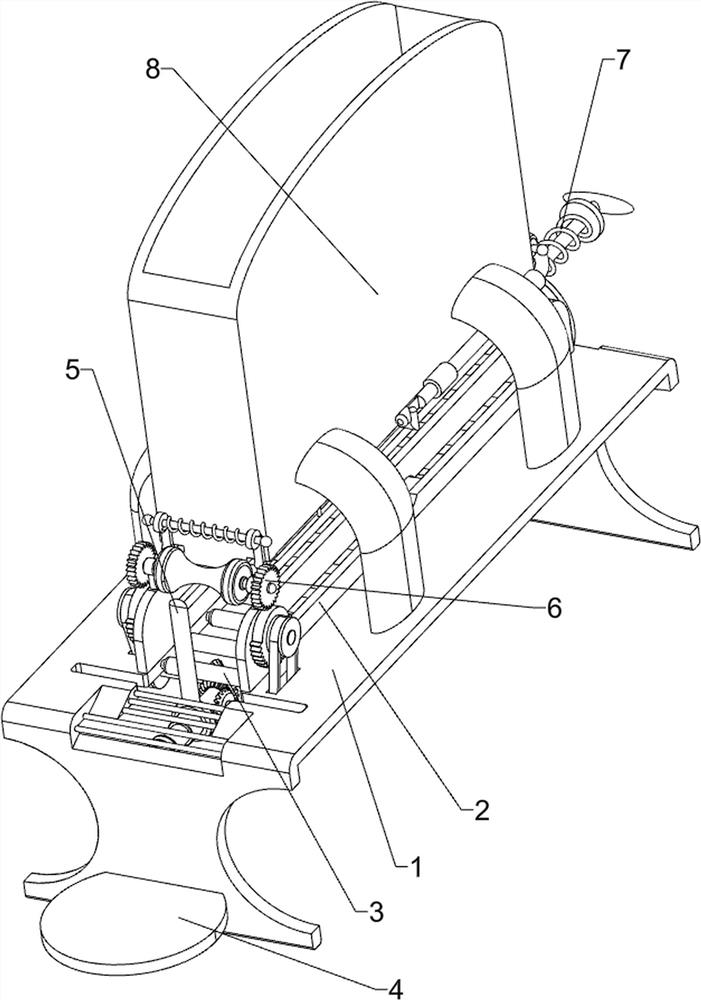
[0023] A clay cutting device for ceramic making, such as Figure 1-2 As shown, it includes a support plate 1, a side plate 2, a sliding roller 3 and a placement plate 4. The top left and right sides of the support plate 1 are connected with side plates 2, and the support plate 1 between the side plates 2 on both sides rotates at even intervals. There are multiple sliding rollers 3 connected in the same way, and the front side of the support plate 1 is connected with a placement plate 4, and also includes a cutting device 5 and a conveying device 6. The cutting device 5 is provided on the support plate 1, and the A conveying device 6 is provided, and the conveying device 6 is connected with the cutting device 5 in transmission.
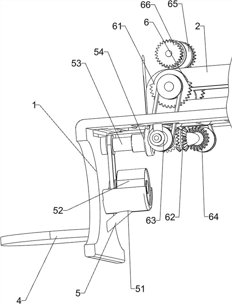
[0024] The cutting device 5 includes a mounting base 51, a motor 52, a rotating shaft 53 and a cutting knife 54, the bottom front side wall of the support plate 1 is connected with the mounting base 51, and the motor 52 is installed on the mounting bas...
Embodiment 2
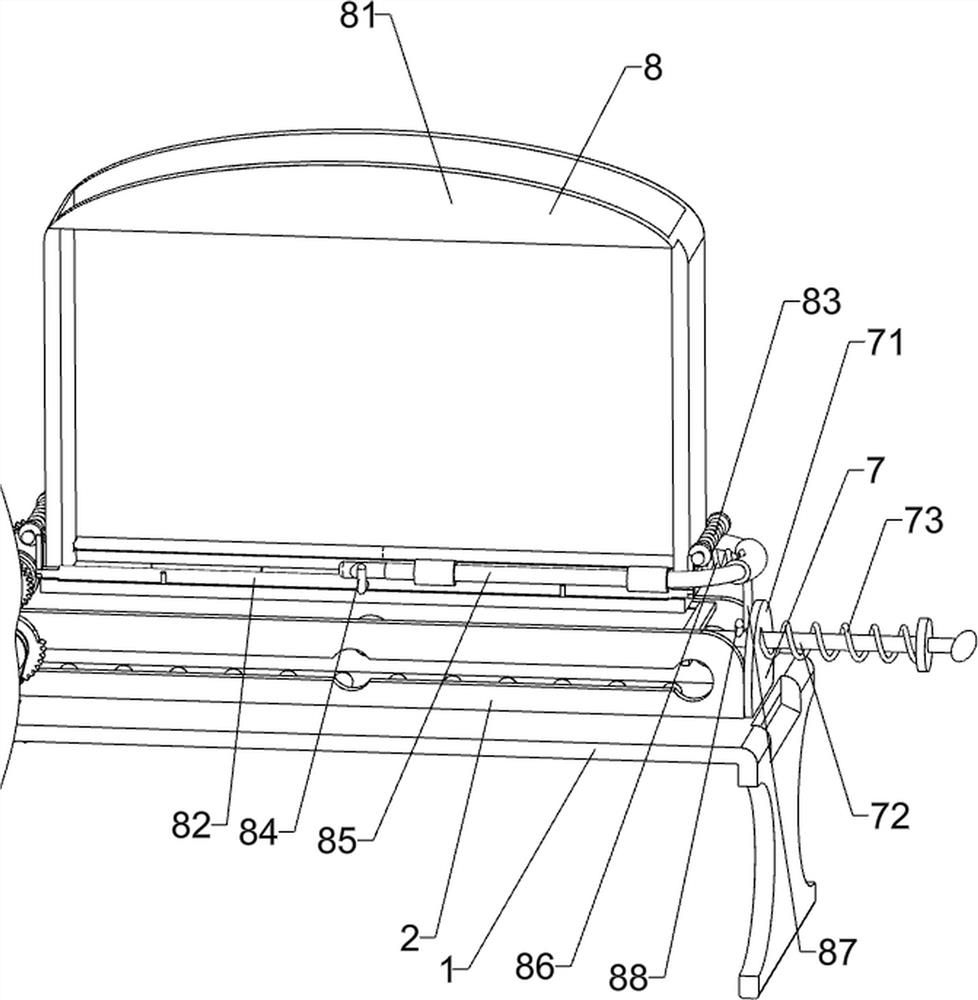
[0028] On the basis of Example 1, such as image 3 As shown, a pusher device 7 is also included. The pusher device 7 includes a connecting plate 71, a T-shaped push rod 72 and a return spring 73. The rear side of the top of the support plate 1 is connected with a connecting plate 71, which is slidably connected There is a T-shaped push rod 72 , which slides and fits with the side plate 2 , and a return spring 73 is connected between the T-shaped push rod 72 and the connecting plate 71 .
[0029] When placing clay, the T-shaped push rod 72 can be pulled to move backward, and the back-moving spring 73 is stretched. When the T-shaped push rod 72 moved to the limit, the clay can be placed. After placing, unclamp the T-shaped push rod 72. The T-shaped push rod 72 resets under the effect of the back-moving spring 73, and the T-shaped push rod 72 resets can push the clay into contact with the inner concave roller 65, so that the clay does not need to be manually pushed into contact w...
Embodiment 3
[0031] On the basis of Example 2, such as image 3 As shown, also includes a blanking device 8, the blanking device 8 includes a material frame 81, clamp bar 82, pressure spring 83, L-shaped bar 84, U-shaped bar 85, tension spring 86, cross bar 87 and clamping block 88 , the top of the support plate 1 is connected with a material frame 81, the discharge end of the material frame 81 is located above the slide roller 3, and the left and right sides of the bottom of the material frame 81 are slidingly connected with clamping rods 82, and the front and rear sides of the clamping rods 82 on both sides are all slidable. A pressure spring 83 is connected, an L-shaped bar 84 is connected to the clamp bar 82, a U-shaped bar 85 is slidably connected to the rear side of the material frame 81, and the U-shaped bar 85 cooperates with the L-shaped bar 84, and the U-shaped bar 85 and the material frame 81 A tension spring 86 is connected between them, a block 88 is connected to the top of th...
PUM
 Abstract
Description
Claims
Application Information
 - R&D
- Intellectual Property
- Life Sciences
- Materials
- Tech Scout
- Unparalleled Data Quality
- Higher Quality Content
- 60% Fewer Hallucinations
Browse by: Latest US Patents, China's latest patents, Technical Efficacy Thesaurus, Application Domain, Technology Topic, Popular Technical Reports.
© 2025 PatSnap. All rights reserved.Legal|Privacy policy|Modern Slavery Act Transparency Statement|Sitemap|About US| Contact US: help@patsnap.com