
Flexible pneumatic finger and grabbing device

A pneumatic finger and flexible technology, applied in the direction of manipulators, chucks, manufacturing tools, etc., can solve the problems of small output force, loose structure of flexible starting fingers, and inability to bear large loads, etc., to achieve the effect of compact overall structure

Pending Publication Date: 2020-10-30
SOUTH UNIVERSITY OF SCIENCE AND TECHNOLOGY OF CHINA
View PDF0 Cites 2 Cited by
  • Summary
  • Abstract
  • Description
  • Claims
  • Application Information

AI Technical Summary

Problems solved by technology

[0004] In view of the above-mentioned deficiencies in the prior art, the purpose of the present invention is to provide a flexible pneumatic finger and a grasping device, aiming to solve the problem that the existing flexible starting finger has a loose structure, a small output force, and cannot bear a large load

Method used


Image

  • Flexible pneumatic finger and grabbing device
  • Flexible pneumatic finger and grabbing device
  • Flexible pneumatic finger and grabbing device

Examples


Embodiment Construction

[0029] The present invention provides a flexible pneumatic finger and a grasping device. In order to make the purpose, technical solution and effect of the present invention clearer and clearer, the present invention will be further described in detail below. It should be understood that the specific embodiments described here are only used to explain the present invention, not to limit the present invention.

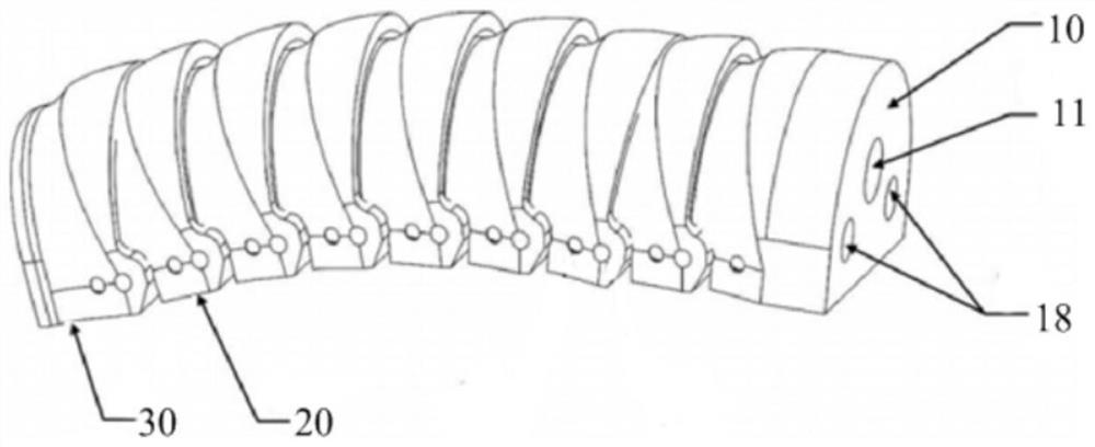
[0030] see figure 1 and figure 2 , the present invention provides a flexible pneumatic finger, as shown in the figure, it includes sequentially hinged first structural unit 10, several second structural units 20 and third structural units 30, the first structural unit 10, several The second structural unit 20 and the third structural unit 30 are hinged to form an internal cavity, and a latex airbag 40 is arranged in the internal cavity, and the latex airbag 40 passes through the ventilation hole provided on the first structural unit 10 11 is connected with trachea 12...


PUM


Abstract

The invention discloses a flexible pneumatic finger and a grabbing device. The flexible pneumatic finger comprises a first structural unit, a plurality of second structural units and a third structural unit which are sequentially hinged, wherein the first structural unit, the second structural units and the third structural unit are hinged to form an internal cavity; a latex balloon is arranged inthe internal cavity; and the latex balloon is connected with an air pipe through a vent hole in the first structural unit. The overall structure of the flexible pneumatic finger is more compact; by means of the first structural unit, the second structural units and the third structural unit, a modular design and an application concept can be realized; and the load bearing capacity of the flexiblepneumatic finger is one magnitude order higher than that of a bent flexible soft driver in the same size.

Description

technical field [0001] The invention relates to the field of pneumatic fingers, in particular to a flexible pneumatic finger and a grabbing device. Background technique [0002] Pneumatic fingers in the industry are mainly divided into two categories, one is the rigid pneumatic finger with cylinder piston as the transmission mechanism, which is characterized by linear power output and can withstand large loads. The disadvantage is reflected in the bloated structure of such a mechanical system , not suitable for grasping flexible objects; the other type is flexible pneumatic fingers made of flexible materials such as silica gel and latex as the main body, and imposing special constraints. It is characterized by good grasping surface adaptability, It has no destructive effect on the object to be grasped. The disadvantage is that such a soft material driver usually forms a system with other hard structures to complete the grasping task. Its structure is loose, the output force ...

Claims


Application Information

Patent Timeline
IPC IPC(8): B25J15/08B25J15/02
CPCB25J15/02B25J15/08
Inventor 薛文博葛锜
Owner SOUTH UNIVERSITY OF SCIENCE AND TECHNOLOGY OF CHINA
Learn More