


Quick Research
Generate reliable direction feasibility study reports for your R&D in just a few steps.

Technical Q&A
Discover and master advanced knowledge NOW. Basics, ideas, possibilities, all at once.

Find Solutions
As an expert in R&D theories, this can generate solutions to your technical problems instantly.

Evaluate Feasibility
Analyze your overall solution with one click, know your potential R&D risks in advance.

Monitor Landscape
Get weekly tech updates, stay abreast of the latest tech innovations and key insights.
Machining process for improving roughness of inner hole of porous plate of chemical equipment
A processing technology and perforated plate technology, which is applied in the field of processing technology for improving the inner hole roughness of perforated plates in chemical equipment, can solve the problems of low inner hole roughness of perforated plates, etc. The effect of ensuring liquidity
- Summary
- Abstract
- Description
- Claims
- Application Information
AI Technical Summary
Problems solved by technology
Method used
Image

Examples
Embodiment 1
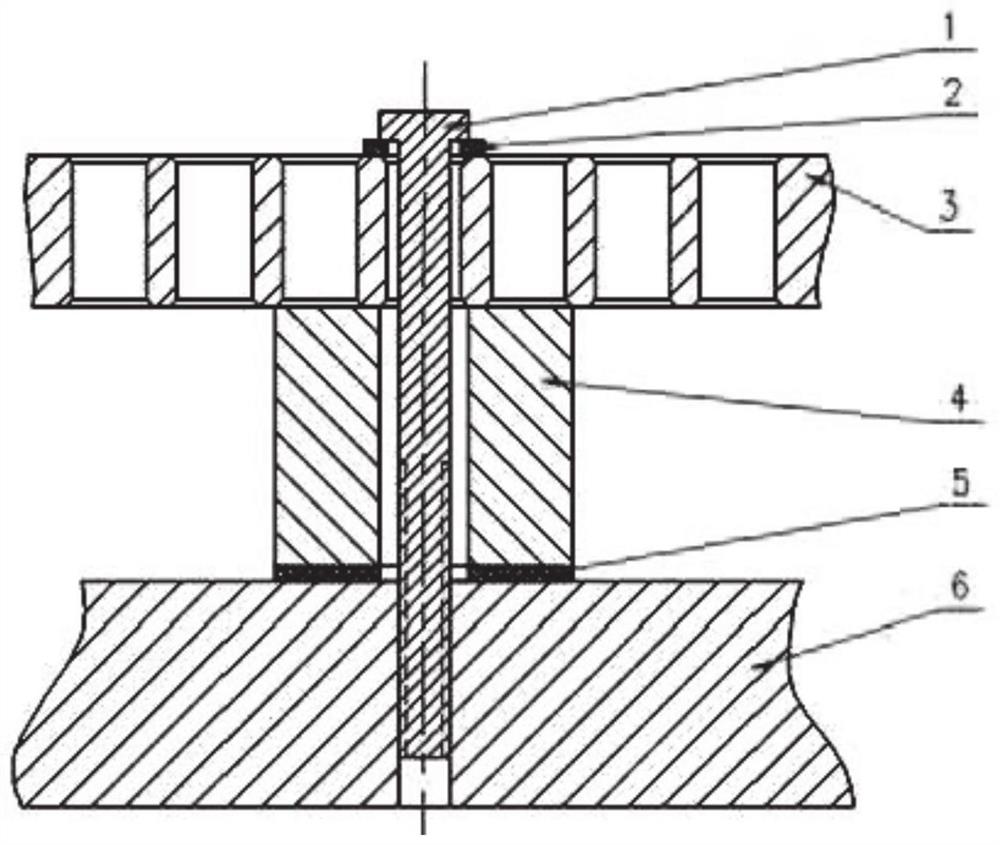
[0044] Fixed perforated plate: eg figure 2 As shown, the diameter of the perforated plate (3) is 2460mm, and the thickness is 20mm. According to the diameter of the perforated plate (3), the size of the positioning plate (6) is determined to be 2600*2600*30mm, and the inner hole layout of the perforated plate (3) is 14mm. Arrange in a regular triangle, determine the position of the drilling and tapping according to the layout of the inner holes of the perforated plate, the horizontal distance is 15 hole distances, and the longitudinal distance is 16 rows, determine the number of drilling and tapping required, and prepare a corresponding number of nylon blocks ( 4), bolts (1) and washers (2). Afterwards, fix the positioning (6) plate on the workbench, align and determine the coordinate center, and carry out scribing, drilling, chamfering and tapping according to the planned layout. Bond the corresponding number of nylon blocks (4) to the positions of the bolt holes with AB gl...
Embodiment 2
[0047] The mode of fixing perforated plate is the same as embodiment 1;
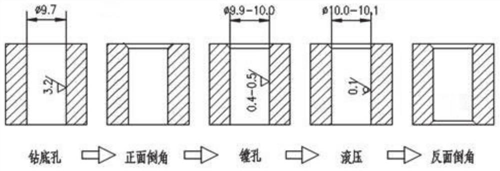
[0048] Machining the inner hole of the perforated plate: use a 9.7mm internal cooling drill to process the bottom hole of the perforated plate 3, the rotational speed of the internal cooling drill S=1200r / min, and the feed rate F=90mm / min to obtain a 9.7mm bottom hole, and the inner hole of the bottom hole The hole roughness reaches Ra3.2; then use the chamfering drill to perform front chamfering, the chamfering drill speed S=900r / min, the feed speed F=120mm / min, after processing, the angle of 1x45° is obtained; then use S08K-SCLCR06 The boring tool performs boring on the inner hole, the speed S=750r / min, the feed speed F=100mm / min, and a smooth 9.9mm-10mm finished inner hole is obtained, and the inner hole roughness reaches Ra0.4-0.5; and then Use the mirror rolling tool to roll the inner hole, the mirror rolling tool speed S=900r / min, the feed speed F=125mm / min, to obtain the inner hole with an inner d...
Embodiment 3
[0050] The mode of fixing perforated plate is the same as embodiment 1;
[0051] Machining the inner hole of the perforated plate: use a 9.7mm internal cooling drill to process the bottom hole of the perforated plate 3, the rotational speed of the internal cooling drill S=1350r / min, and the feed rate F=100mm / min to obtain a 9.7mm bottom hole, and the inner hole of the bottom hole The hole roughness reaches Ra3.2; then use the chamfering drill for front chamfering, the chamfering drill speed S=1000r / min, the feed speed F=140mm / min, after processing, the angle of 1x45° is obtained; then use S08K-SCLCR06 The boring tool performs boring on the inner hole, the speed S=850r / min, the feed speed F=120mm / min, and a smooth 9.9mm-10mm finished inner hole is obtained, and the inner hole roughness reaches Ra0.4-0.5; and then Use the mirror rolling tool to roll the inner hole, the mirror rolling tool speed S=1000r / min, the feed speed F=150mm / min, get the inner hole with an inner diameter of...
PUM
| Property | Measurement | Unit |
|---|---|---|
| diameter | aaaaa | aaaaa |
| thickness | aaaaa | aaaaa |
| thickness | aaaaa | aaaaa |
Abstract
Description
Claims
Application Information
 - R&D Engineer
- R&D Manager
- IP Professional
- Industry Leading Data Capabilities
- Powerful AI technology
- Patent DNA Extraction
Browse by: Latest US Patents, China's latest patents, Technical Efficacy Thesaurus, Application Domain, Technology Topic, Popular Technical Reports.
© 2024 PatSnap. All rights reserved.Legal|Privacy policy|Modern Slavery Act Transparency Statement|Sitemap|About US| Contact US: help@patsnap.com