Automatic control welding platform for coaxial cable and 2M joint

A technology of coaxial cable and welding platform, applied in welding equipment, manufacturing tools, auxiliary devices, etc., can solve the problem of low efficiency, interruption of communication between substation and ground control system, and affecting the monitoring and operation of power grid equipment by dispatchers and network control personnel. And other issues

Active Publication Date: 2020-10-30
STATE GRID SHANDONG ELECTRIC POWER +1
View PDF10 Cites 1 Cited by
  • Summary
  • Abstract
  • Description
  • Claims
  • Application Information

AI Technical Summary

Problems solved by technology

Routers, optical transceivers, interface conversion equipment, and PCM servers are all connected with 2M cables. The 2M cables can only be connected to communication equipment after the 2M connectors are connected. Communication interruption affects the monitoring and operation of grid equipment by dispatchers and network controllers
[0003] At present, when the coaxial cable is connected to the 2M head, soldering is required to fix it. In the actual processing process, the welder generally uses a soldering iron in one hand and a solder wire in the other hand to weld the 2M head. However, due to Welding personnel are unable to fix the 2M head, and there may be a lot of debris in the welding place. The 2M head is prone to rolling during the welding process, which is very inconvenient and inefficient to weld. Even if the welding is completed, the welded 2M head may still exist Due to the instability between the coaxial cable and the 2M head during the welding process, poor welding contact (virtual welding) quality problems are caused, which affects the normal connection of the line

Method used


Image

  • Automatic control welding platform for coaxial cable and 2M joint
  • Automatic control welding platform for coaxial cable and 2M joint
  • Automatic control welding platform for coaxial cable and 2M joint

Examples


Embodiment Construction

[0032] The present invention will be further described below in conjunction with the accompanying drawings and embodiments. It should be pointed out that the following detailed description is exemplary and intended to provide further explanation to the present application. Unless defined otherwise, all technical and scientific terms used herein have the same meaning as commonly understood by one of ordinary skill in the art to which this application belongs.

[0033] It should be noted that the terminology used here is only for describing specific implementations, and is not intended to limit the exemplary implementations according to the present application. As used herein, unless the context clearly dictates otherwise, the singular is intended to include the plural, and it should also be understood that when the terms "comprising" and / or "comprising" are used in this specification, they mean There are features, steps, operations, means, components and / or combinations thereo...


PUM


Abstract

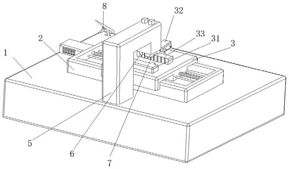
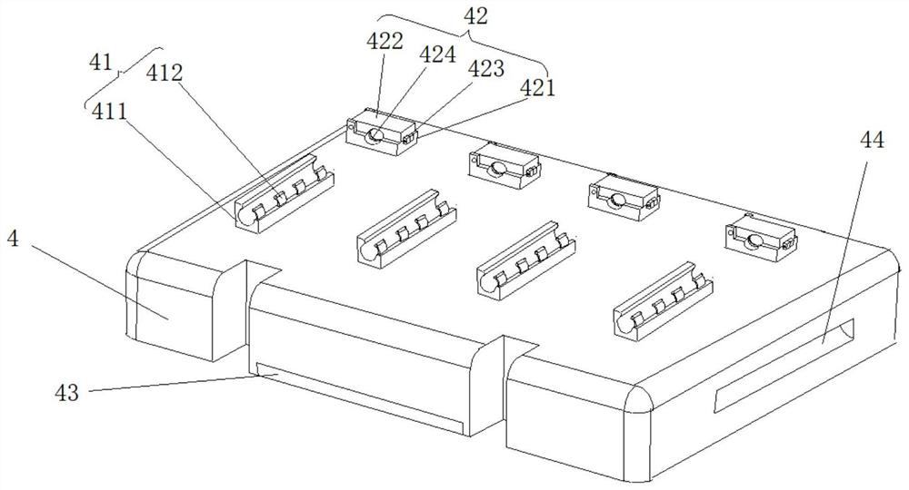
The invention discloses an automatic control welding platform for a coaxial cable and a 2M joint and belongs to the technical field of circuit welding equipment. The automatic control welding platformfor the coaxial cable and the 2M joint comprises a machine table, a servo guide rail, a movable seat, a clamp seat, 2M elastic clamps, coaxial cable clamps, a support frame, extending-and-contractingarms, a welding mechanism and a structured light locating and distance measurement mechanism. The machine table is provided with the servo guide rail. The movable seat is arranged on the servo guiderail in a sliding manner. The clamp seat is detachably fixed to the movable seat and provided with the 2M elastic clamps and the coaxial cable clamps. The support frame is fixed to the machine table and provided with the two extending-and-contracting arms. The two extending-and-contracting arms are connected with the welding mechanism and the structured light locating and distance measurement mechanism correspondingly. The automatic control welding platform for the coaxial cable and the 2M joint has the beneficial effects that welding precision and welding efficiency are high, operation is convenient to conduct, and the automatic control welding platform is applicable to massive coaxial cable and 2M joint welding.

Description

technical field [0001] The invention relates to the field of power line welding equipment, in particular to an automatic control coaxial cable and 2M head welding platform. Background technique [0002] With the rapid development of power dispatching automation technology, coaxial cables, as an indispensable communication device, are widely used in power systems. Routers, optical transceivers, interface conversion equipment, and PCM servers are all connected with 2M cables. The 2M cables can only be connected to communication equipment after the 2M connectors are connected. Communication interruption affects the monitoring and operation of grid equipment by dispatchers and network controllers [0003] At present, when the coaxial cable is connected to the 2M head, soldering is required to fix it. In the actual processing process, the welder generally uses a soldering iron in one hand and a solder wire in the other hand to weld the 2M head. However, due to Welding personnel...

Claims


Application Information

Patent Timeline
Patent Type & Authority Applications(China)
IPC IPC(8): B23K3/08B23K1/005B23K1/00
CPCB23K3/087B23K3/08B23K1/0056B23K1/0016
Inventor 吴军梁栋修成林管清琴刘淑磊张纪伟戴昭彭淦榕孙金华徐霞张兵
Owner STATE GRID SHANDONG ELECTRIC POWER
Why Eureka
Try Eureka