
Electric spindle shaft core assembly, air-floating electric spindle and drilling rig

An electric spindle and air bearing technology, applied in maintenance and safety accessories, metal processing mechanical parts, metal processing equipment, etc., can solve the problems of low vibration performance of the main shaft, unstable vibration performance of the main shaft, etc., and achieve the effect of low vibration performance

Active Publication Date: 2021-12-14
GUANGZHOU HAOZHI ELECTROMECHANICAL
View PDF0 Cites 0 Cited by
  • Summary
  • Abstract
  • Description
  • Claims
  • Application Information

AI Technical Summary

Problems solved by technology

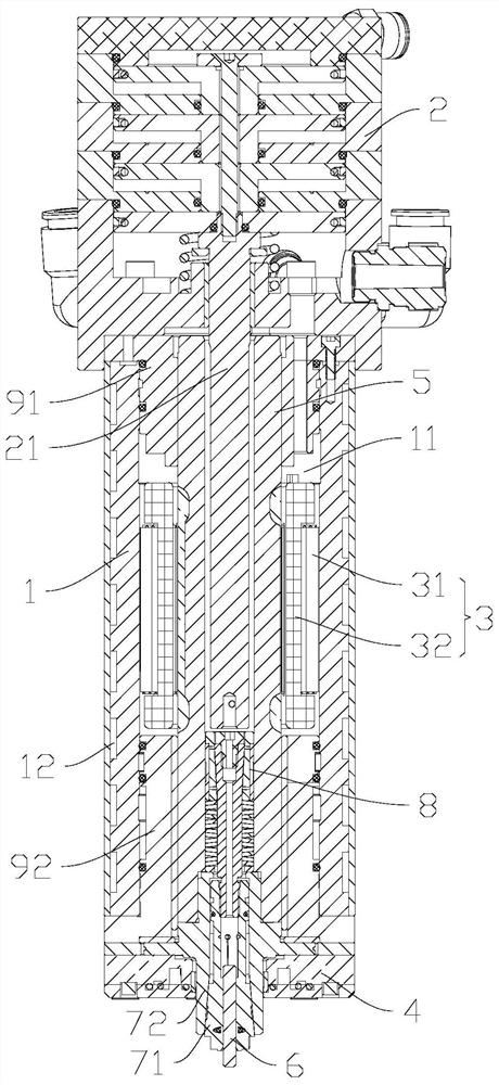
[0004] The purpose of the present invention is to solve at least one of the technical problems in the prior art, to provide an electric spindle shaft core assembly, an air-floating electric spindle and a drilling rig, and to innovatively adopt a new type of shaft that can compensate for changes in temperature and centrifugal expansion. The bully structure effectively solves the problem of unstable vibration performance of the spindle caused by the quality eccentricity of the clamping mechanism during the high-speed rotation of the shaft core, and realizes the low vibration performance characteristics of the spindle

Method used


Image

  • Electric spindle shaft core assembly, air-floating electric spindle and drilling rig
  • Electric spindle shaft core assembly, air-floating electric spindle and drilling rig
  • Electric spindle shaft core assembly, air-floating electric spindle and drilling rig

Examples


Embodiment Construction

[0037] This part will describe the specific embodiment of the present invention in detail, and the preferred embodiment of the present invention is shown in the accompanying drawings. Each technical feature and overall technical solution of the invention, but it should not be understood as a limitation on the protection scope of the present invention.

[0038] In the present invention, if there is a description of directions (up, down, left, right, front and back), it is only for the convenience of describing the technical solution of the present invention, rather than indicating or implying that the referred technical features must have specific Orientation, construction and operation in a particular orientation, therefore should not be construed as limiting the invention.

[0039] In the present invention, "several" means one or more, "multiple" means more than two, "greater than", "less than", "exceeding", etc. are understood as excluding the original number; "above", "belo...


PUM


Abstract

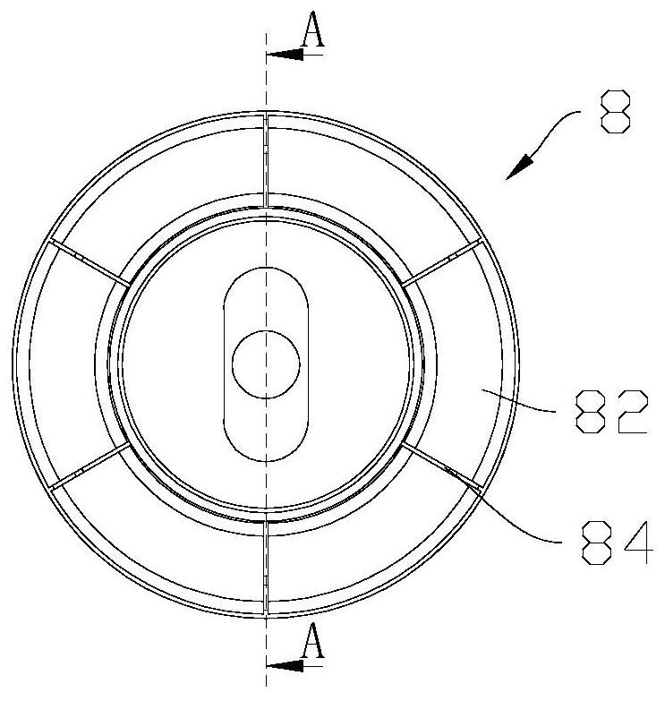
The invention discloses an electric spindle shaft core assembly, an air-floating electric spindle and a drilling machine, comprising: a shaft core with an inner hole of the shaft core; a tool clamping mechanism including a chuck inner core and a chuck sleeve, and the chuck sleeve is connected to the The end of the shaft core; the shaft bully mechanism, including a sliding sleeve and a sliding sleeve core, the sliding sleeve is arranged in the inner hole of the shaft core, the sliding sleeve is set on the outside of the sliding sleeve core, and the sliding sleeve has Tapered inner hole, the sliding sleeve core has an outer tapered surface matched with the tapered inner hole, the sliding sleeve core is connected with the inner core of the chuck; elastic parts are arranged on the sliding sleeve and the Between the collet sleeves, the elastic member is against the sliding sleeve. The innovative adoption of a new type of shaft bully structure that can compensate for changes in temperature and centrifugal expansion changes, effectively solves the problem of unstable vibration performance of the spindle caused by mass eccentricity of the clamping mechanism during the high-speed rotation of the shaft core, and realizes the characteristics of low vibration performance of the spindle.

Description

technical field [0001] The invention is used in the field of rotary processing, and in particular relates to an electric spindle core assembly, an air-floating electric spindle and a drilling machine. Background technique [0002] The vigorous development of optoelectronic industry, integrated circuits and consumer electronics products has higher and higher requirements for drilling processing technology in PCB industry. There are two main factors restricting the development of processing technology. One is the development of drilling technology; the other is the implementation of drilling technology. The core component of hole machining is the accuracy of the air-floating electric spindle; the research shows that the performance index of the core component air-floating electric spindle is the key factor affecting the quality of drilling processing, such as the torque of the spindle motor, the vibration speed and amplitude, and the dynamic elongation of the shaft core. amoun...

Claims


Application Information

Patent Timeline
Patent Type & Authority Patents(China)
IPC IPC(8): B23B19/02B23Q1/38B23Q11/00
CPCB23Q1/70B23Q11/0032B23Q1/38
Inventor 朱胜利汤丽君汤秀清
Owner GUANGZHOU HAOZHI ELECTROMECHANICAL
Learn More