Double-spindle core-moving type numerical control lathe

A CNC lathe and dual-spindle technology, which is applied in the field of lathes, can solve problems such as affecting the shape of the workpiece and the jamming of the tool movement process.

Active Publication Date: 2020-10-30
东莞市华盛鑫恒通实业有限公司
View PDF13 Cites 0 Cited by
  • Summary
  • Abstract
  • Description
  • Claims
  • Application Information

AI Technical Summary

Problems solved by technology

[0003] At present, there is a double-spindle core-moving CNC lathe, which will cut off a large amount of waste chips under the friction between the workpiece and the tool. These waste chips splash around in the CNC lathe, causing some waste chips to fall on the moving

Method used


Image

  • Double-spindle core-moving type numerical control lathe
  • Double-spindle core-moving type numerical control lathe
  • Double-spindle core-moving type numerical control lathe

Examples


Embodiment 1

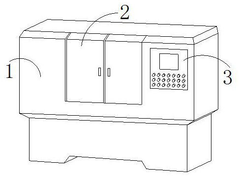
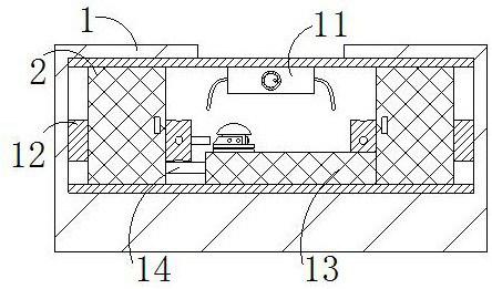
[0029] The present invention provides a dual-spindle core-moving CNC lathe, the structure of which includes a lathe 1, a protective door 2, and a control panel 3. The protective door 2 is connected to the front side of the lathe 1 through movable engagement, and the control panel 3 is embedded. On the front surface of the lathe 1, the lathe 1 includes a coolant tank 11, a main shaft 12, a support block 13, and a rotating shaft 14. The top of the coolant tank 11 is fixed on the upper inner wall of the lathe 1, and the main shaft 12 is engaged by a movable Connected to the left and right inner walls of the lathe 1, the support block 13 is installed at the bottom of the lathe 1, the right end of the rotating shaft 14 is connected to the left side of the support block 13 through a gap, the main shaft 12 has two, and the rotating shaft 14 is connected with the motor, and The cooling pipes at both ends of the coolant tank 11 can be raised and contracted, which is beneficial to the ro...

Embodiment 2

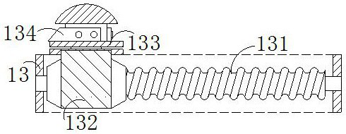
[0035]In the figure, the guide block a2 includes a limiting cavity a21, a temporary storage groove a22, an air bag a23, and a brush plate a24. The limiting cavity a21 is embedded in the guide block a2, and the temporary storage groove a22 and the guide block a2 The upper surface is an integrated structure, the airbag a23 is embedded in the bottom of the guide block a2, the brush plate a24 runs through the bottom of the guide block a2 and the top of the brush plate a24 is welded to the bottom of the fixed rod a1, and the temporary storage groove a22 faces inward Concave, and the brush plate a24 is made of rubber material and bends to the left at the same time, which is beneficial for the brush plate a24 to wipe the surface of the moving shaft 131 when the positioning block 132 moves, and avoids jamming when the positioning block 132 moves.

[0036] In the figure, the temporary storage groove a22 includes a guide plate m1, a bump m2, and a limiting block m3, the guide plate m1 is...


PUM


Abstract

The invention discloses a double-spindle core-moving type numerical control lathe. The double-spindle core-moving type numerical control lathe structurally comprises a lathe, a protective door and a control panel, the protective door is connected to the front side of the lathe through movable clamping, and the control panel is embedded and fixed on the front surface of the lathe. The double-spindle core-moving type numerical control lathe has the beneficial effects that a motor drives a rotating shaft to rotate, so that a moving shaft rotates, a positioning block horizontally moves under the engagement of the moving shaft and a positioning cavity, the position of a cutter is changed, a workpiece is cut conveniently, the surface of the moving shaft is brushed by a brush plate under the movement of the positioning block, scraps are prevented from being clamped between the positioning block and the moving shaft, the positioning block is prevented from moving and blocking, the scraps inside a temporary storage groove fall on a bulge through a guide plate, the scraps squeeze a convex block downwards under the action of gravity, so that the convex block presses the limiting rod downwardsto rotate around a fixed shaft, air in an air bag is squeezed to blow the scraps brushed by the brush plate downwards, the scraps are prevented from falling back to the surface of the moving shaft, the scraps are removed, and the positioning block is moved conveniently.

Description

technical field [0001] The invention relates to the field of lathes, in particular to a double-spindle core-moving numerical control lathe. Background technique [0002] The CNC lathe is a device that can automatically process the processed parts according to the pre-programmed processing program. The core-moving CNC lathe is a CNC lathe that can move the workpiece axially. Its advantage is that the processing diameter is small and the length is long. The double-spindle drives the workpiece to rotate at high speed, and the workpiece is constantly rubbed against the tool, and the workpiece is cut out of the required shape on time. [0003] At present, there is a double-spindle core-moving CNC lathe, which will cut off a large amount of waste chips under the friction between the workpiece and the tool. These waste chips splash around in the CNC lathe, causing some waste chips to fall on the moving axis. As a result, the waste remaining on the moving shaft is stuck between the...

Claims


Application Information

Patent Timeline
IPC IPC(8): B23B3/30B23B25/00
CPCB23B3/30B23B25/00Y02P70/10
Inventor 王佩
Owner 东莞市华盛鑫恒通实业有限公司
Why Eureka
Try Eureka