
Biological deodorization box shell protection type steel structure

A protective, steel-structured technology, applied in the direction of dispersed particle separation, air quality improvement, chemical instruments and methods, etc., can solve problems such as poor firmness of the box

Pending Publication Date: 2020-10-30
朱红良 +1
View PDF0 Cites 0 Cited by
  • Summary
  • Abstract
  • Description
  • Claims
  • Application Information

AI Technical Summary

Problems solved by technology

[0004] In order to solve the defects and deficiencies in the above-mentioned prior art, the present invention provides a device arranged on the surface of the FRP material shell of the biological deodorization box, which can solve the problem of poor firmness of the original box body and greatly improve the The firmness and anti-extrusion performance of the shell; at the same time, this allows the equipment to withstand long-distance transportation, which greatly improves the safety and guarantees the overall firmness, which can prolong the service life of the equipment and reduce the cost of the equipment. Maintenance cost biological deodorization box shell protective steel structure
[0006] The invention is arranged on the surface of the FRP material shell of the biological deodorization box, which can solve the problem of poor firmness of the original box, and greatly improve the firmness and anti-extrusion performance of the shell; at the same time, it can make the equipment withstand Long-distance transportation has been greatly improved in safety, and the overall firmness has been guaranteed, which can prolong the service life of equipment and reduce equipment maintenance costs

Method used


Image

  • Biological deodorization box shell protection type steel structure
  • Biological deodorization box shell protection type steel structure
  • Biological deodorization box shell protection type steel structure

Examples


Embodiment Construction

[0028] The present invention will be described in further detail below in conjunction with the accompanying drawings, but it is not intended to limit the protection scope of the present invention.

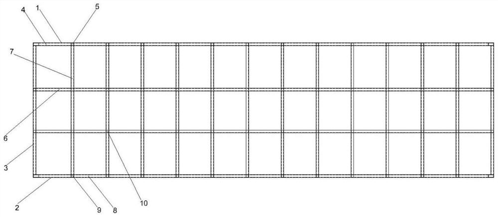
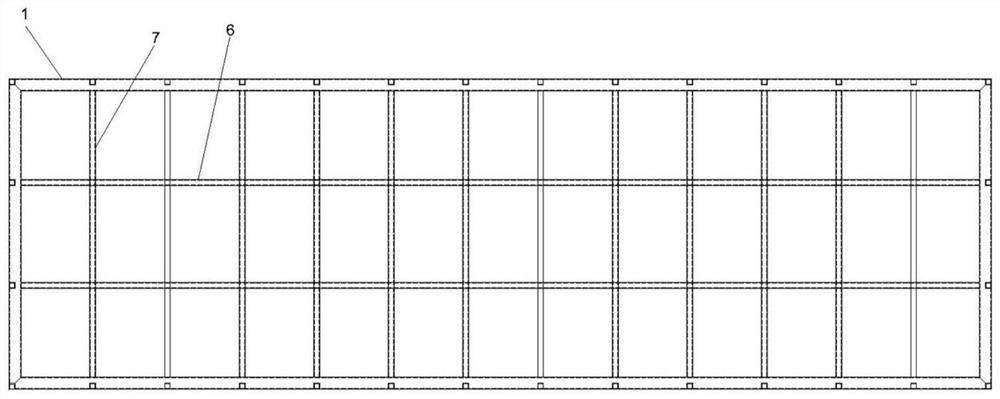
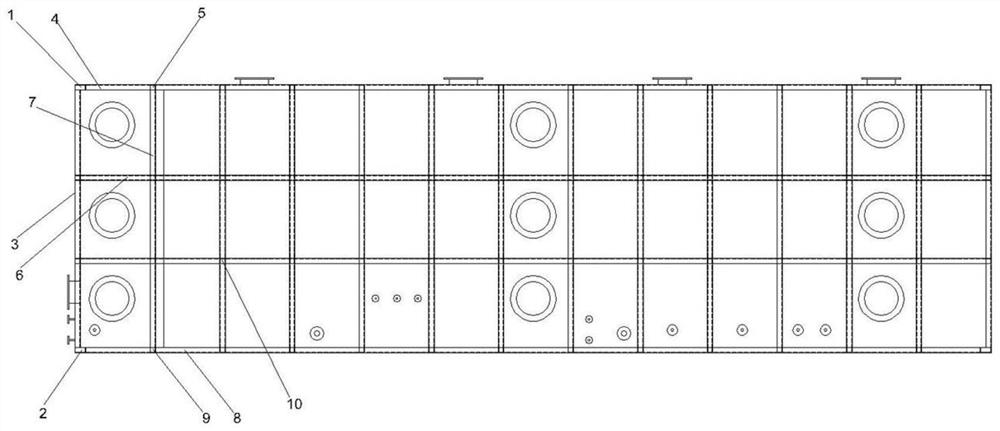
[0029] Such as Figure 1-4 As shown, a biological deodorization box housing protective steel structure includes a top steel face, a bottom steel face and four side steel faces fixed between the top steel face and the bottom steel face. The roof steel structure includes the outer frame of the main roof girder surrounded by four main roof girders 1 and several auxiliary roof girders welded horizontally and vertically on the inner side of the outer frame of the main roof girder. The main beams 1 are welded together, and the bottom steel structure includes the bottom main beam outer frame surrounded by four bottom main beams 2 and several bottom auxiliary beams welded horizontally and vertically on the inner side of the bottom main beam outer frame, and the two bottom auxiliary beams ...


PUM


Abstract

The invention discloses a biological deodorization box shell protection type steel structure. The steel structure comprises a top steel structure surface, a bottom steel structure surface and four side steel structure surfaces, the top steel structure surface comprises a top main beam outer frame and a plurality of top auxiliary beams, the two ends of all the top auxiliary beams are welded with the corresponding top main beams, the bottom steel structure surface comprises a bottom main beam outer frame and a plurality of bottom auxiliary beams, the side steel structure surface comprises a sidemain beam outer frame and a plurality of side auxiliary beams, the two ends of each side auxiliary beam are welded to the corresponding side main beams, and the top steel structure surface, the bottom steel structure surface and the four side steel structure surfaces are each in a square grid shape. The steel structure is arranged on the surface of a FRP shell of the biological deodorization box,so that the firmness and the extrusion resistance of the shell are improved, and meanwhile, the steel structure can endure long-distance transportation, the safety is greatly improved, the overall firmness is guaranteed, the service life of the steel structure can be prolonged, and the maintenance cost of the steel structure is reduced.

Description

technical field [0001] The invention relates to auxiliary facilities of environmental protection equipment, in particular to a shell protective steel structure of a biological deodorization box. Background technique [0002] At present, the application of biological deodorization technology in the field of exhaust gas deodorization is mainly realized by using biological deodorization boxes. The existing problem of the biological deodorization box is that most of the shells are made of a single FRP material, and both the internal structure and the composition of the shell box are roughly the same. The disadvantages of this structure are as follows: a single FRP biological box has defects in operation durability, transportation safety and overall firmness, and it is difficult to resist changes in the surrounding environment, and it is prone to deformation and damage. [0003] Moreover, the biological deodorization box needs to contain a large-volume spray liquid, and also has...

Claims


Application Information

Patent Timeline
IPC IPC(8): B01D53/84
CPCB01D53/84Y02A50/20
Inventor 朱鑫炜郭帅杰朱杭波朱红良
Owner 朱红良
Learn More